CademPVD Software is an intelligent pressure vessel design software which requires minimum inputs. Click here to know more.
Pressure Vessel Design Software
| Index | |
How to design a Pressure Vessel?
On this webpage, you will find a number of tutorials on the design of pressure vessels using CademPVD software.
Scroll to the Top
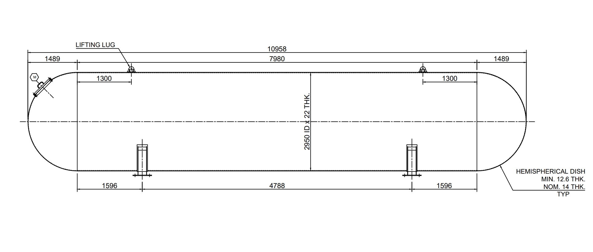
PV-01 - LPG Tank ( Short Version )
Thank you for installing a trial version of CademPVD software.
This is a quick basic pressure vessel demo which you can complete in only six minutes.
We recommend you to try it and get started.
| Design Standard: ASME Section VIII Div. 1 | |||
| Pressure & Temperature | |||
| Operating | Design | Units | |
| Internal pressure | 14.5 | 17.5 | kg/cm2 |
| External pressure | 1.0546 | 1.0546 | kg/cm2 |
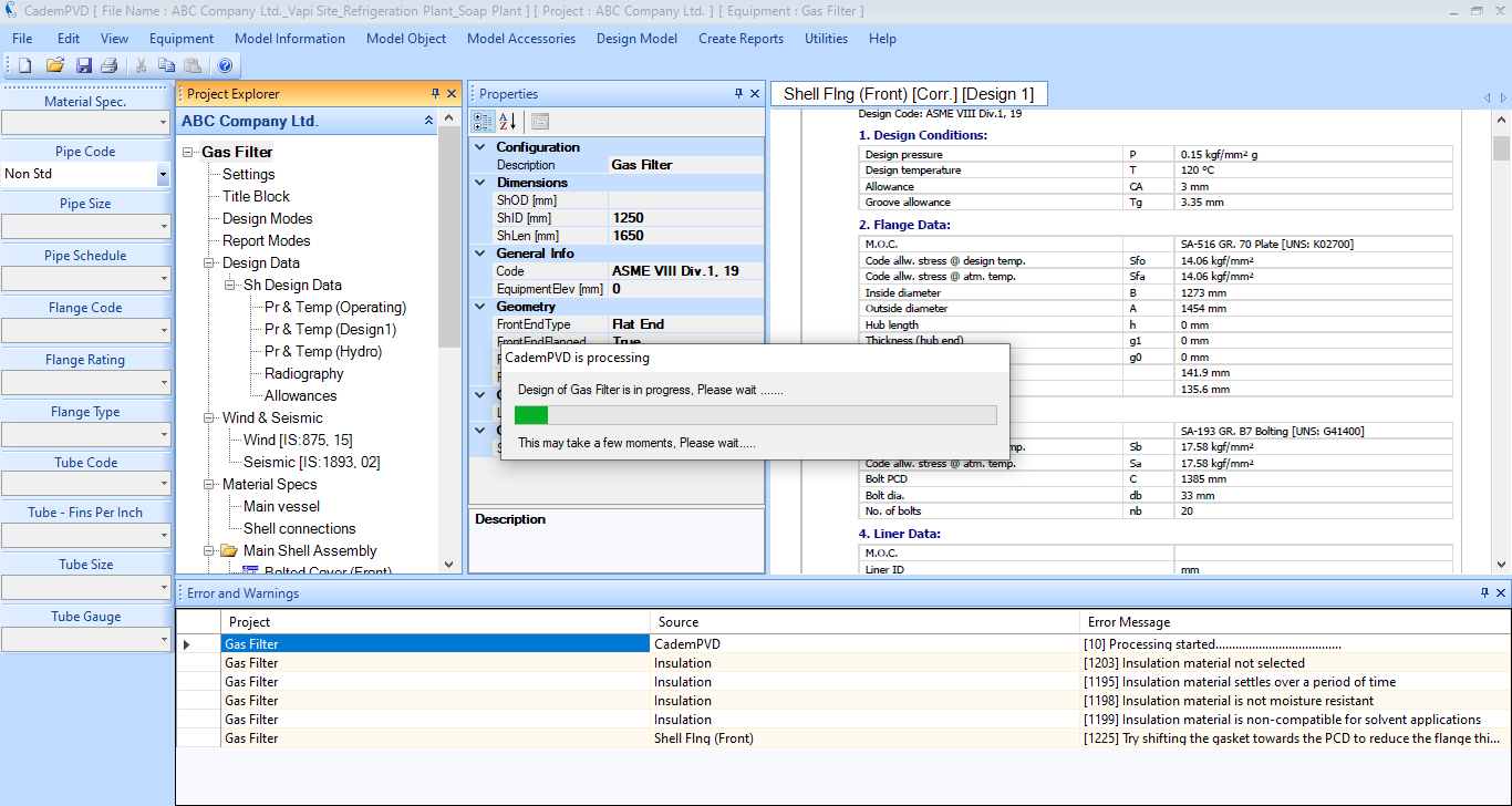
| Max. temperature | 55 | 75 | oC |
| Min. temperature | 10 | -15 | oC |
| Process media | LPG | - | |
| Process density | 490 | kg/m3 | |
| Corrosion allowance | 3 | mm | |
| Polishing allowance | 0 | mm | |
| Materials of construction | |||
| Shell | SA-516-70 Plate | ||
| Head | SA-516-70 Plate | ||
| Manhole / body flange | SA-105 Frgs. | ||
| Support | IS-2062-A Plate | ||
| Anchor bolt | Commercial CS bolt | ||
| Lifting lug | IS-2062-A Plate | ||
You can watch this video of an LPG Tank ASME Pressure Vessel Design using CademPVD software here: 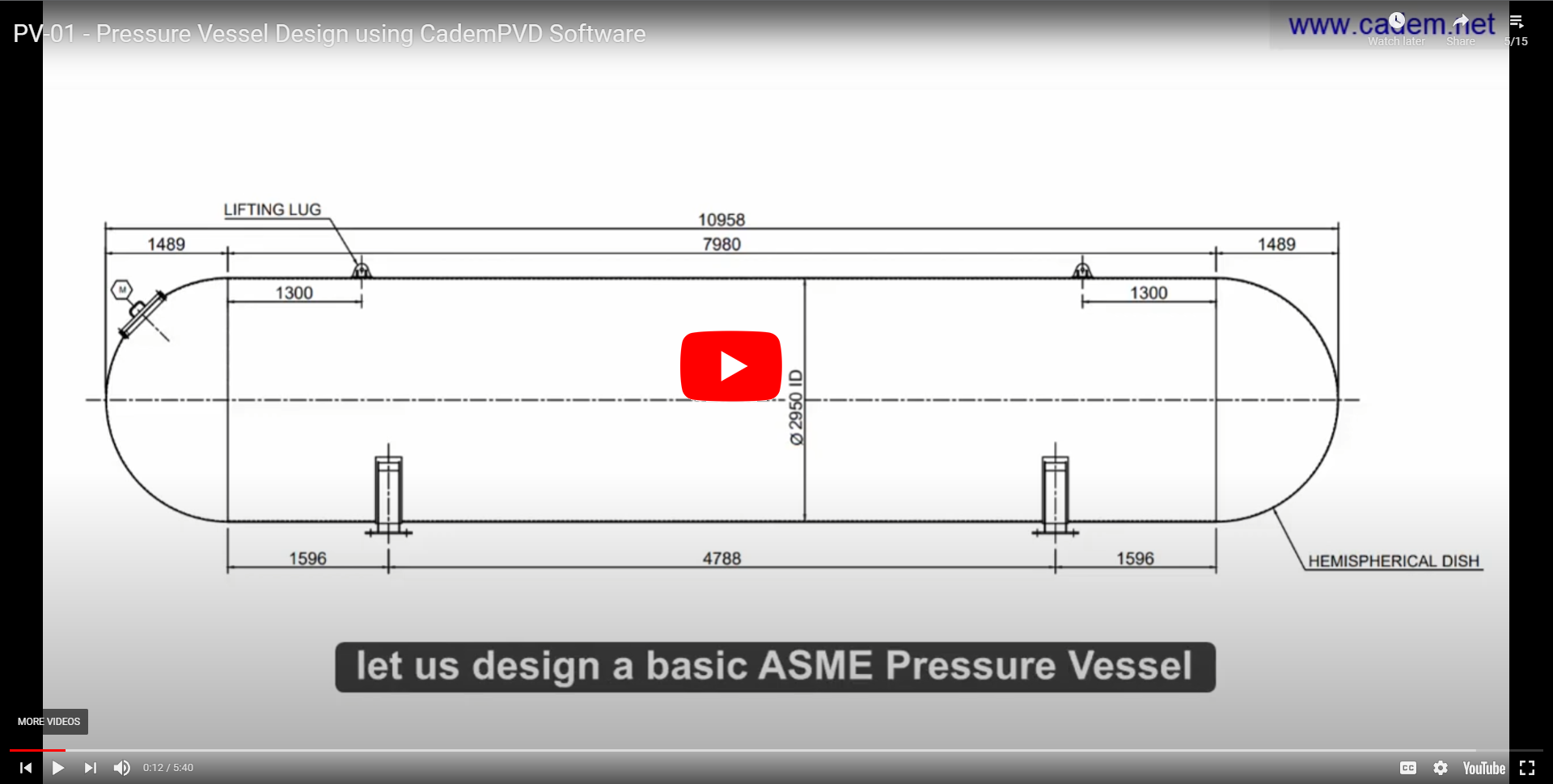
In this short demo, we will design a simple horizontal pressure vessel, LPG Tank, using CademPVD software. To view the addition and design of nozzles, view the longer and more detailed version of this demo.
Let us add the equipment in the project by following the steps below.
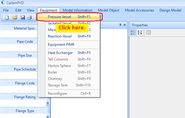
1. Click on the 'Equipment' menu, and select the submenu, 'Pressure Vessel'.
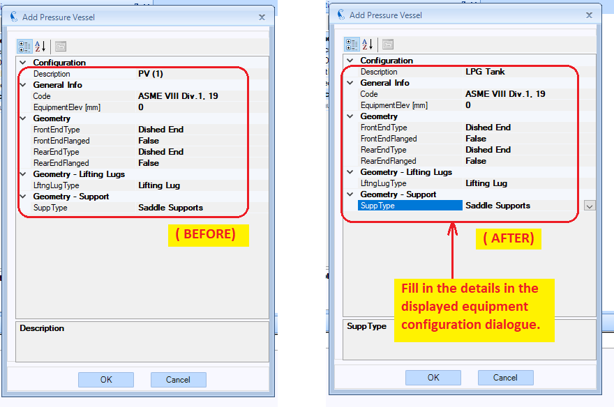
2.Fill in the appropriate details that need to be filled in the displayed equipment configuration dialogue.
For a vessel with its axis horizontal on saddle supports, the front end and the rear end refer to the left end and the right end respectively.
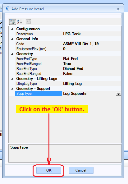
3.Click on the button, 'OK' .
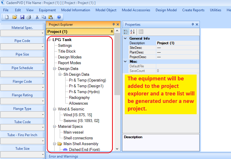
4.The equipment will be added under a newly created project in the Project Explorer, with the equipment name, LPG Tank'.
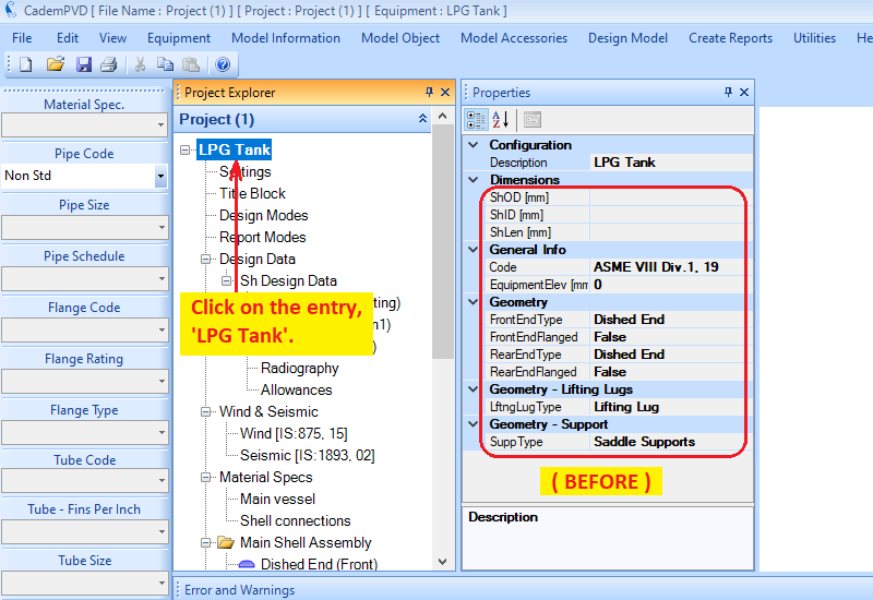
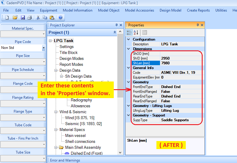
5.Click on the entry, 'LPG Tank', and enter its dimensional details.
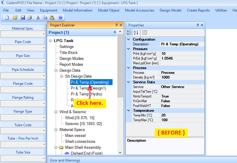
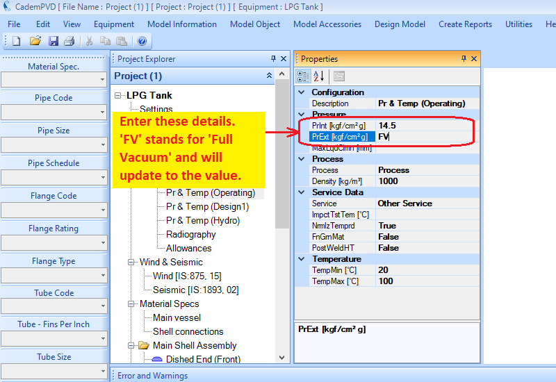
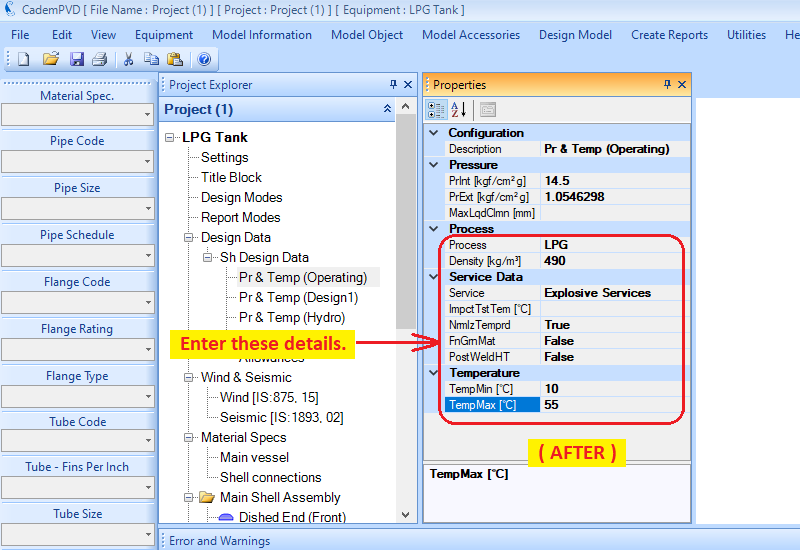
6.The next step is to input the Design Data information. Enter the operating condition information. Please note that the pressure units are kgf/sq.cm. (g) .
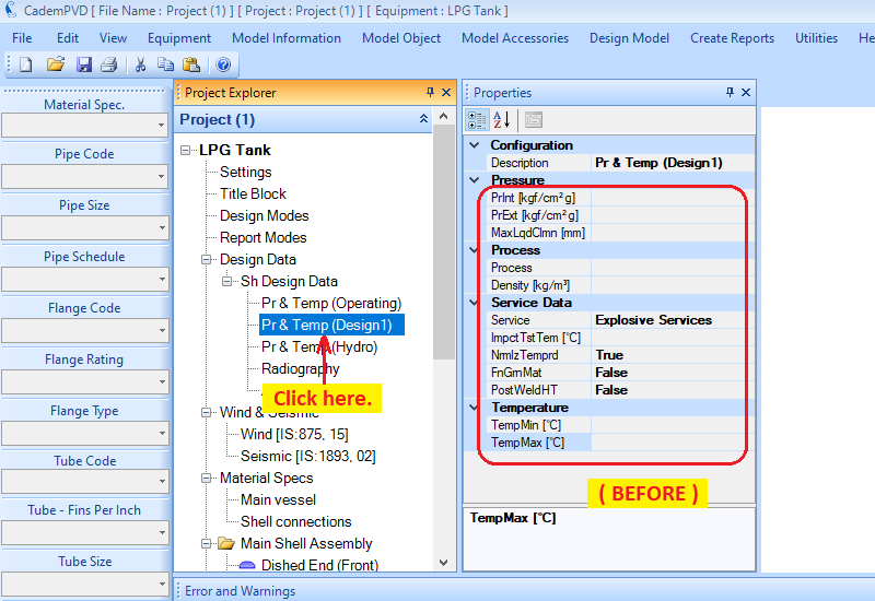
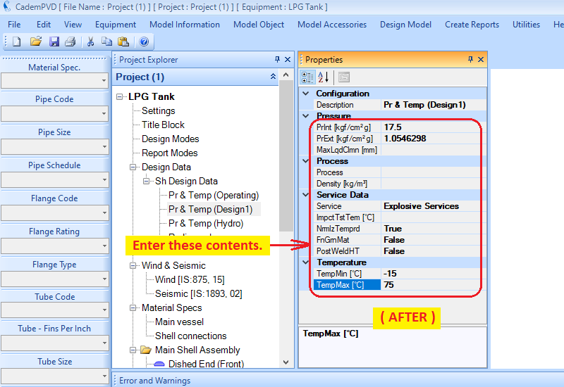
7.Next, enter the design condition information.
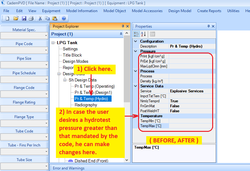
8. In case the user desires a hydro test pressure greater than that required by the code, he can enter it in 'Pr & Temp (Hydro)'.
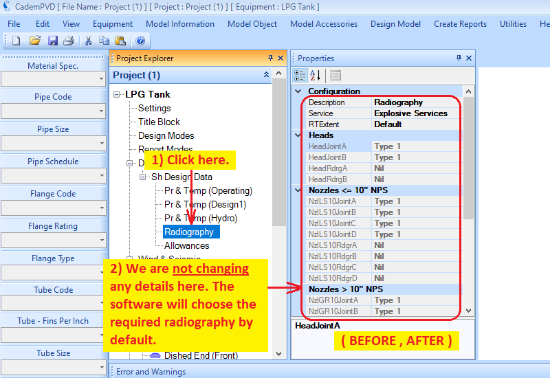
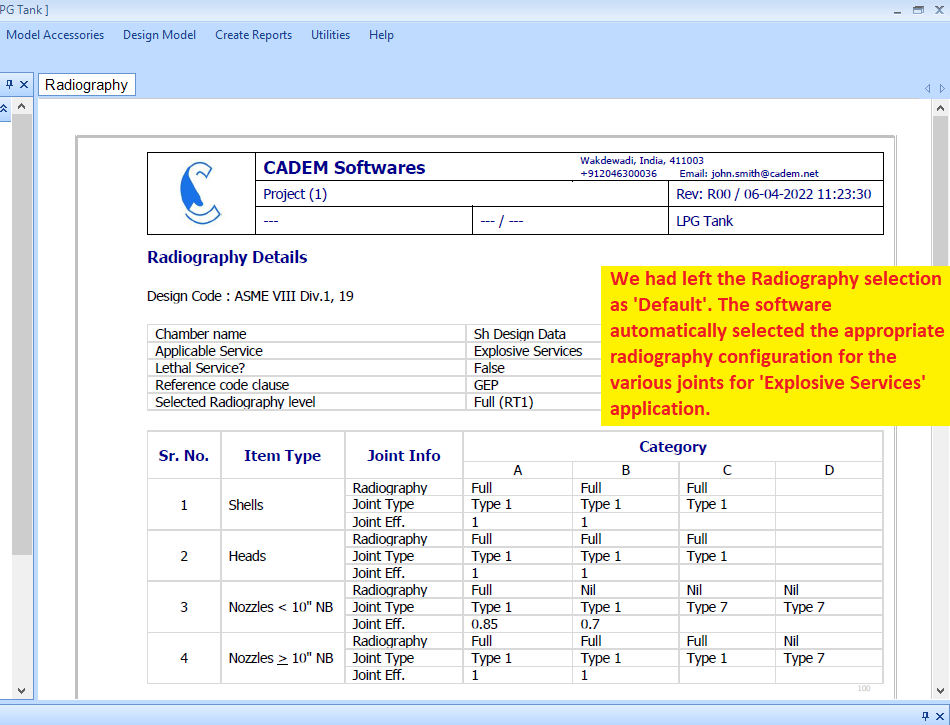
9. We're leaving the Radiography selection as 'Default' . This equipment falls under the 'Explosive Service' usage category.
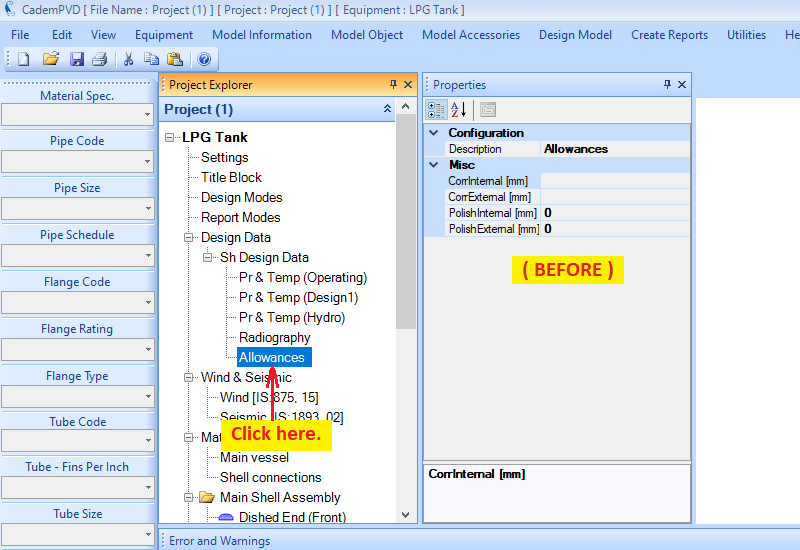
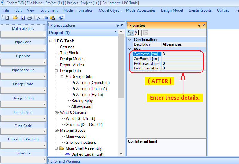
10. Let us add a corrosion allowance of 3 mm.
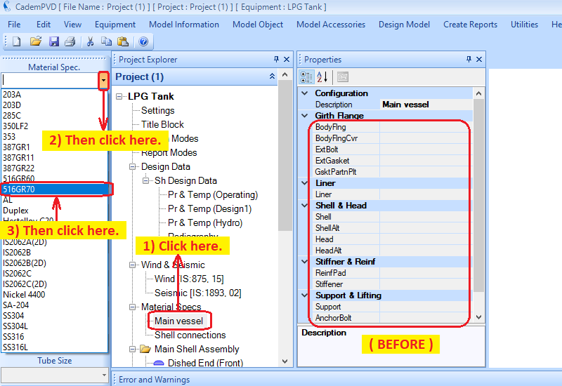
11. The next step is to apply the materials of construction for various components. We use a predefined material spec. for this purpose.
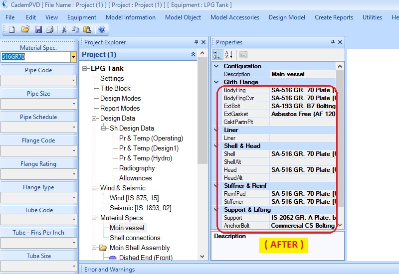
12. Note that until this point, we have entered only the basic minimum inputs. In fact, the only dimensions we have entered are the Shell ID and the Shell Length.
At this stage, we are ready to go ahead and design the equipment.
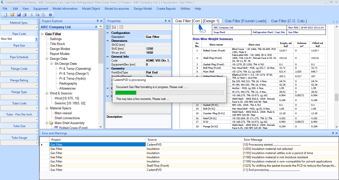
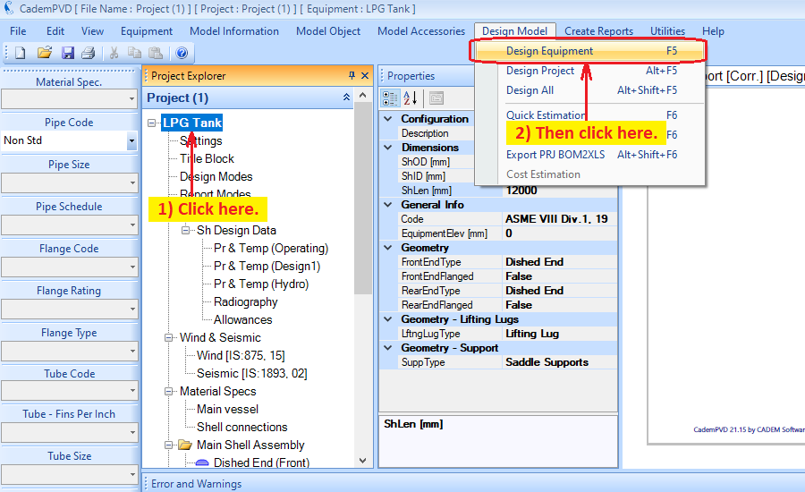
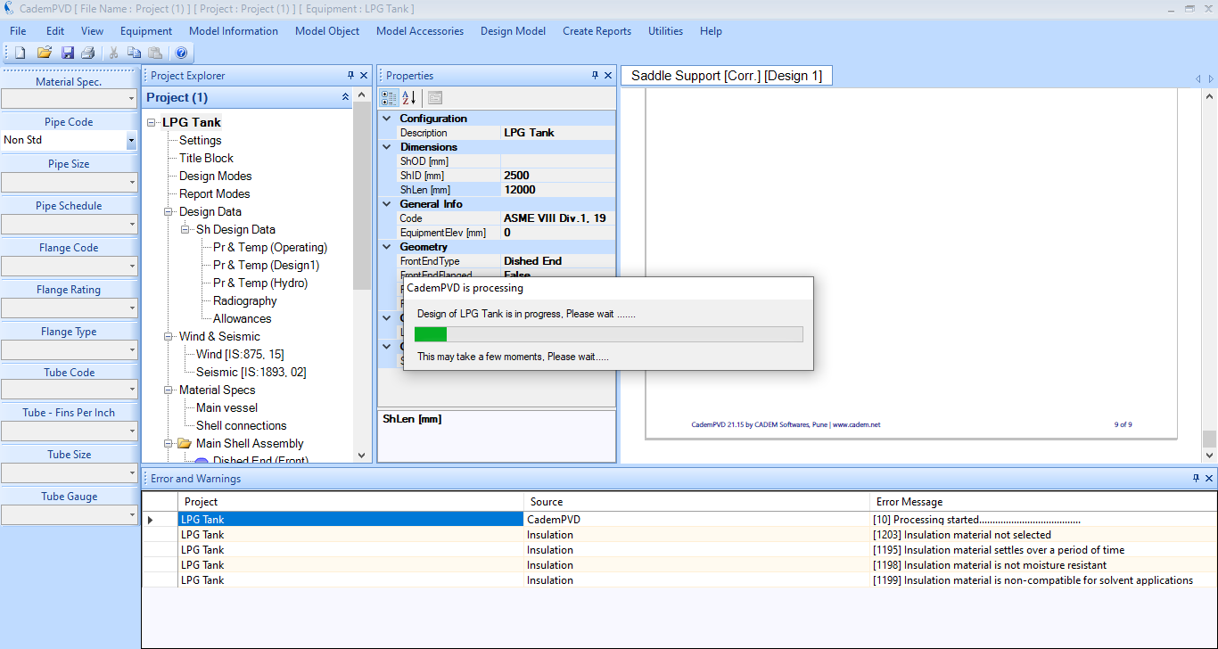
Select the sub-menu ‘Design Equipment’ from the top menu, ‘Design Model’ to design the equipment.
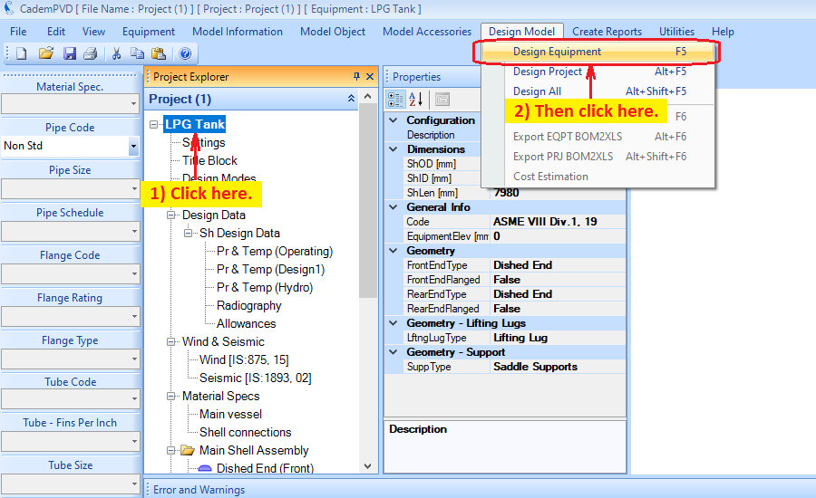
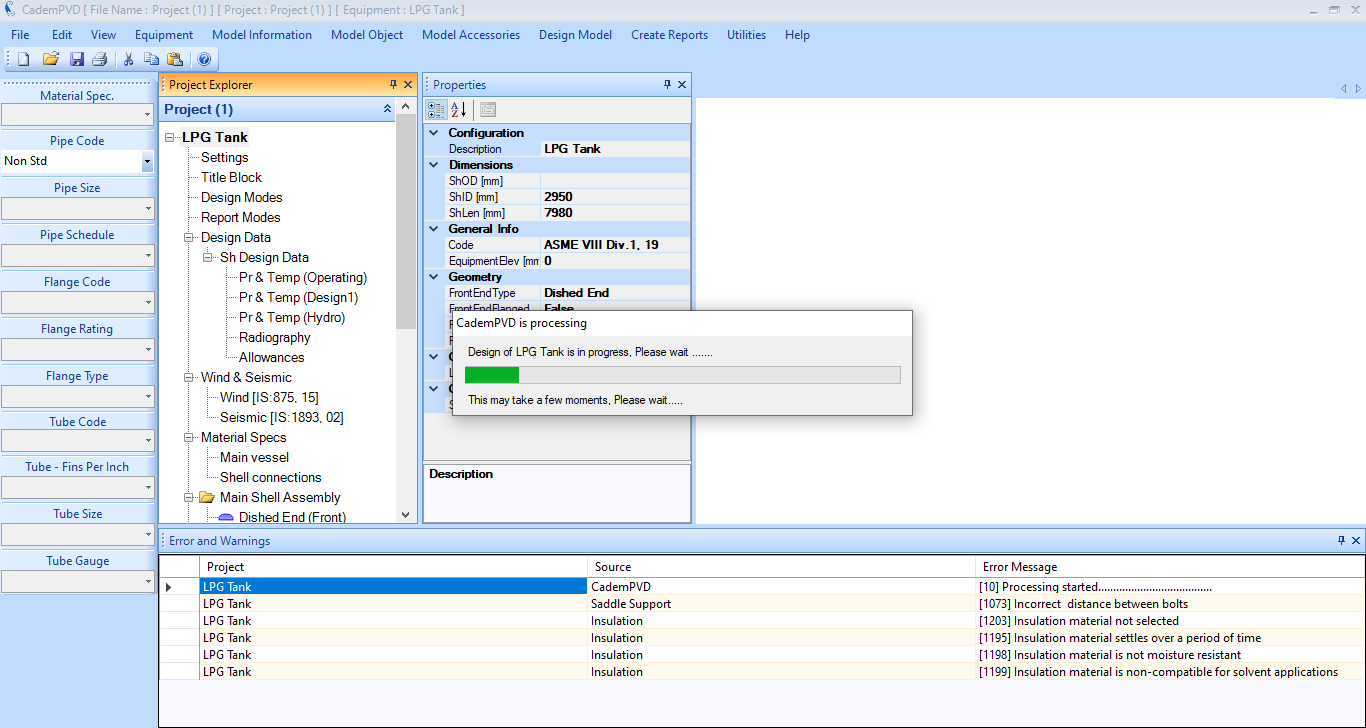
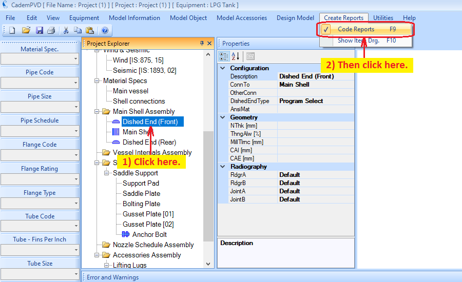
13. Click on the sub-entry ‘Dished End (Front)’, and generate the design report for the Left Side Dished End by selecting the sub-menu ‘Code Reports’ from the top menu, ‘Create Reports’.
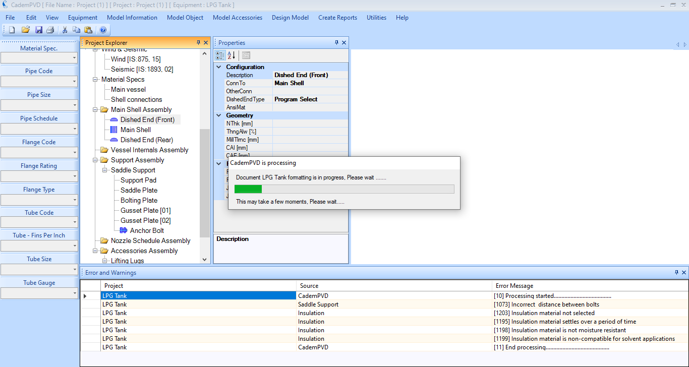
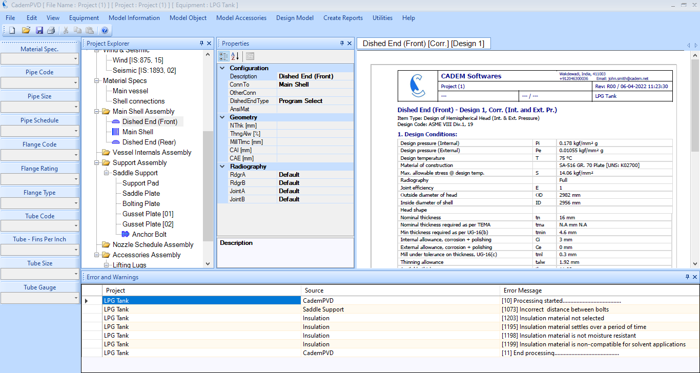
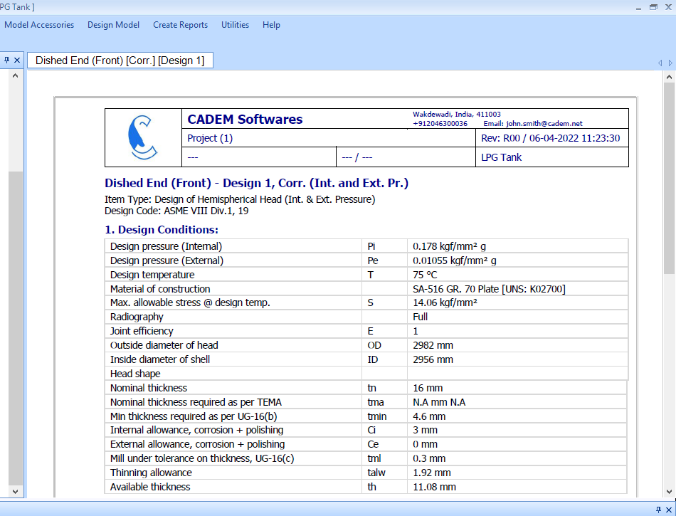
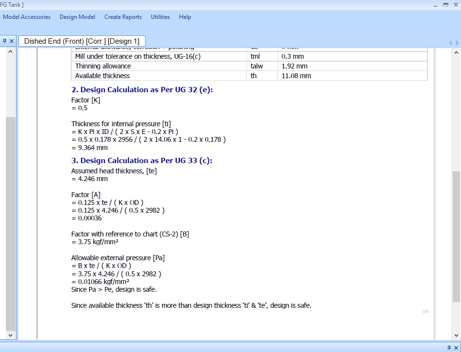
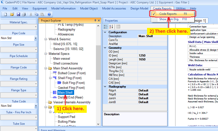
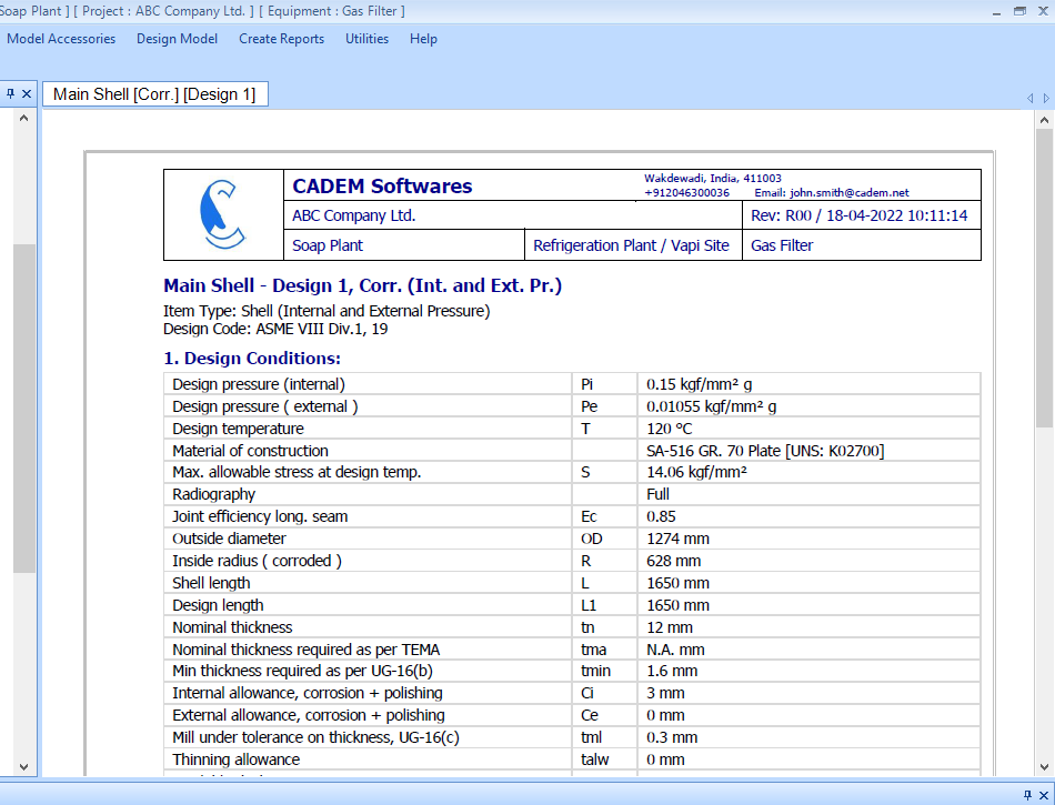
14. Click on the sub-entry ‘Main Shell’, and generate the design report for the Main Shell object by selecting the sub-menu ‘Code Reports’ from the top menu, ‘Create Reports’.
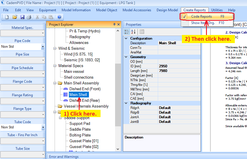
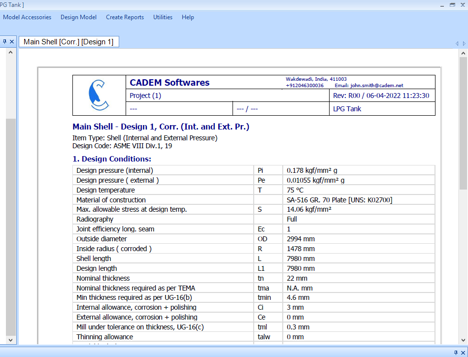
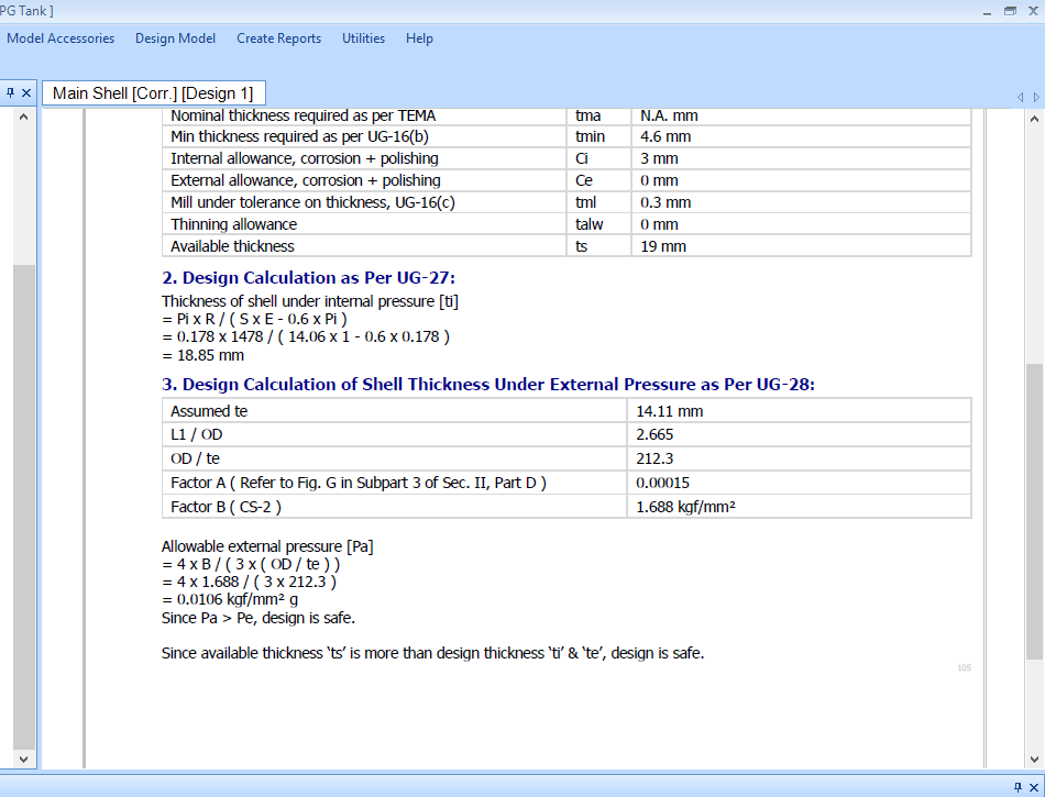
15. Click on the sub-entry ‘Radiography’, and generate its design report.
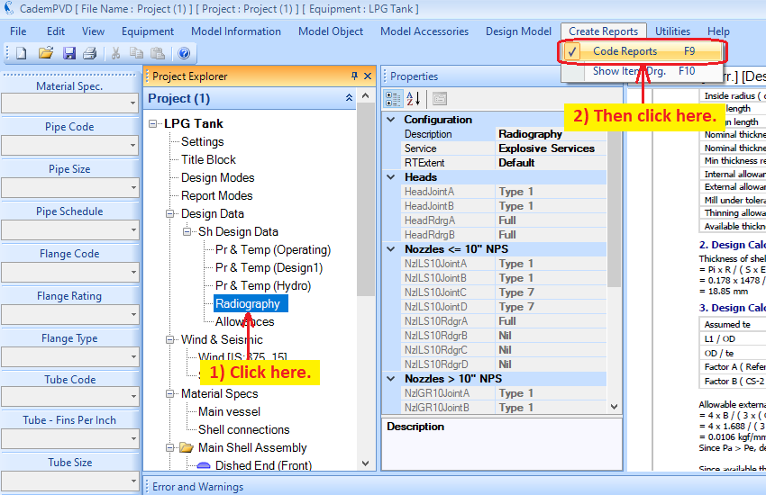
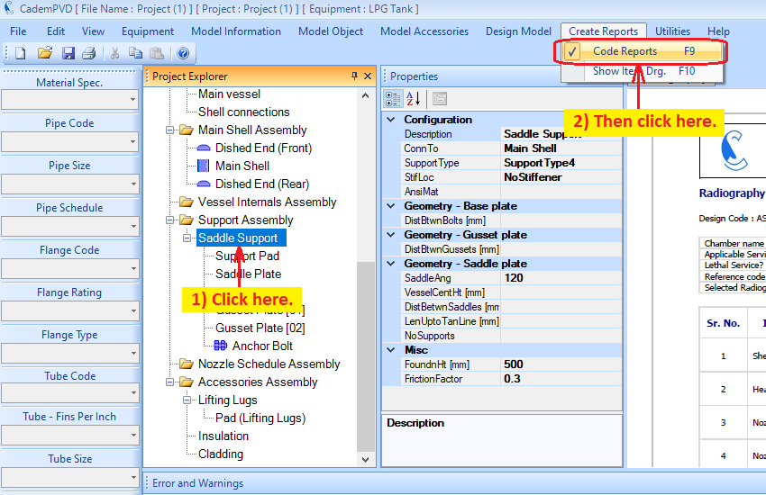
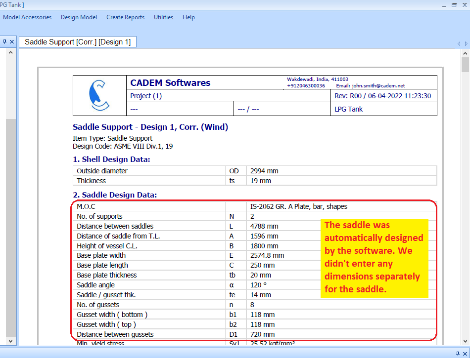
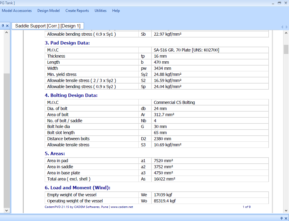
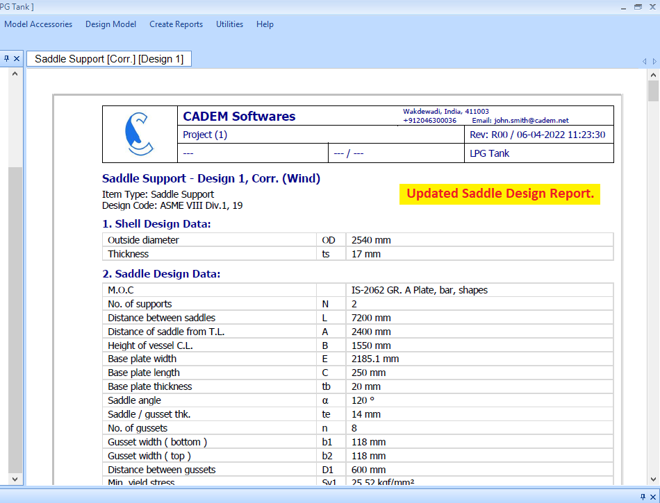
16. Click on the sub-entry ‘Saddle Support’, and generate its design report.
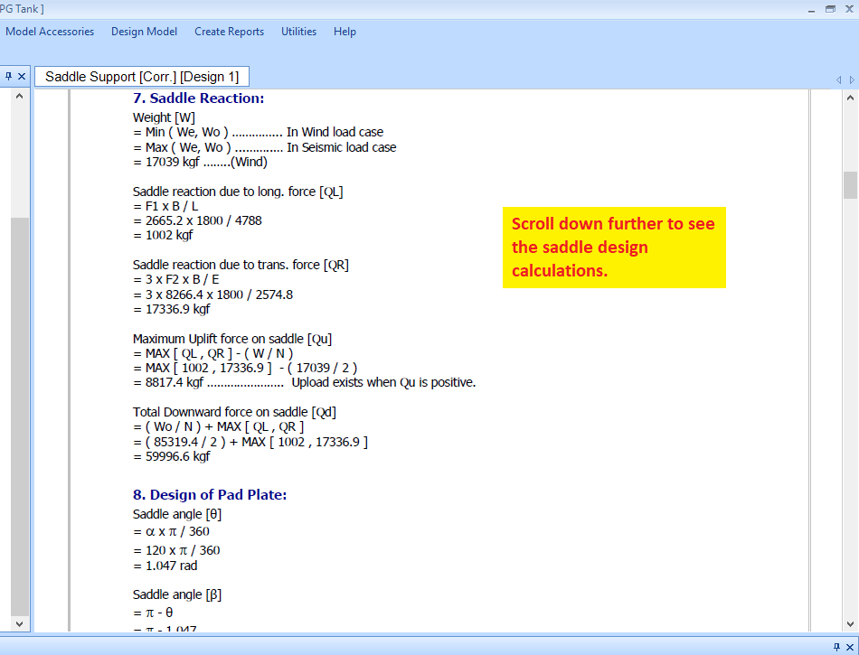
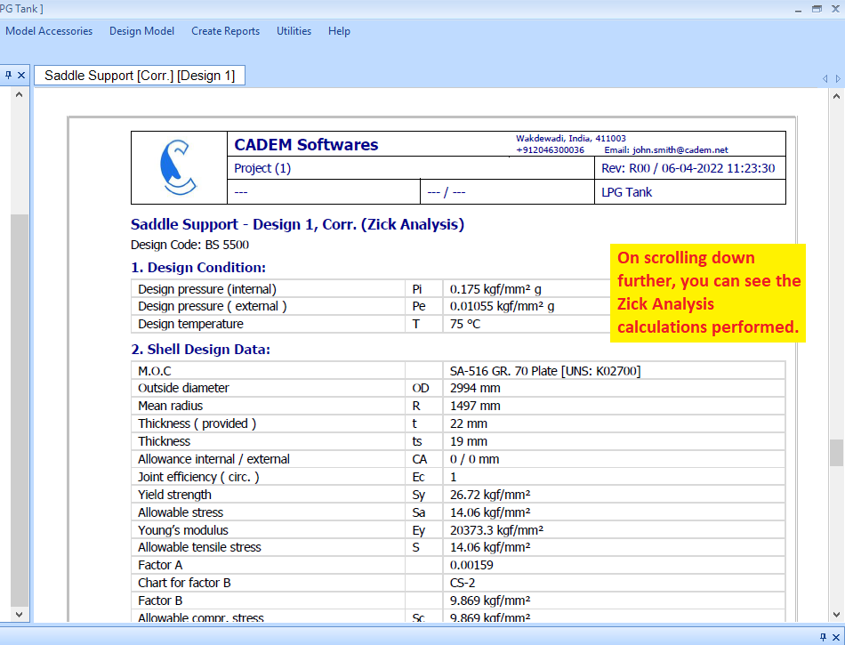
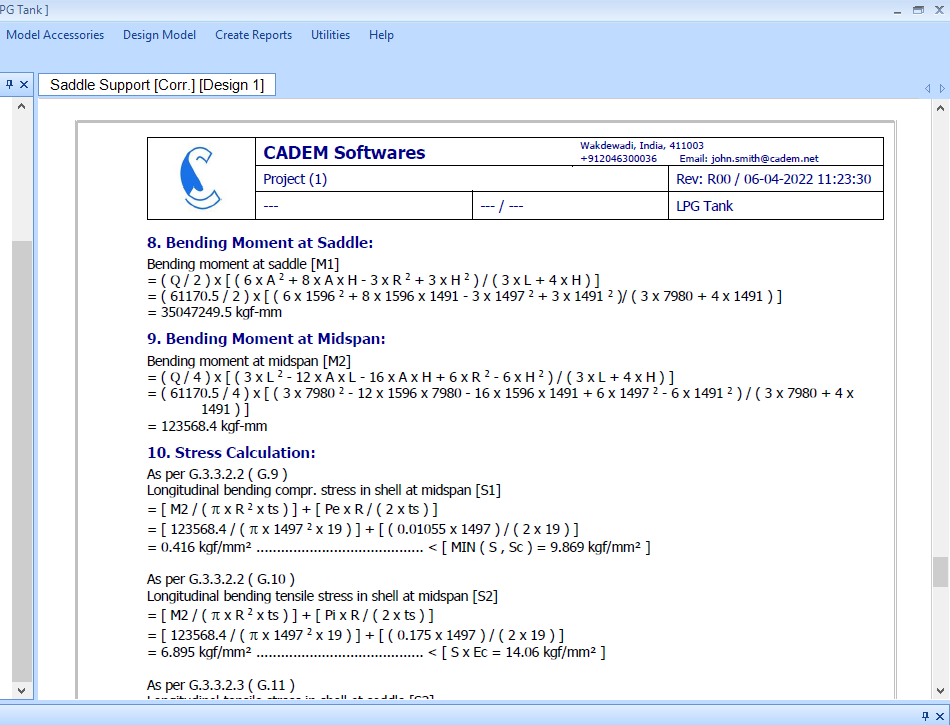
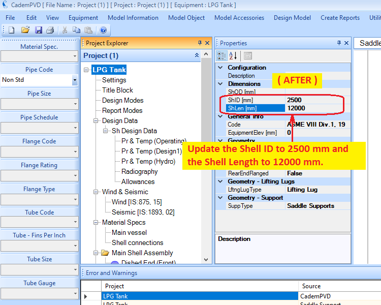
17. Let us change the Shell ID and Shell Length, and redesign the equipment.
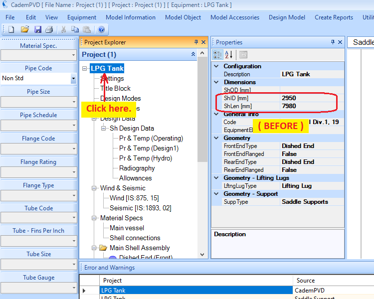
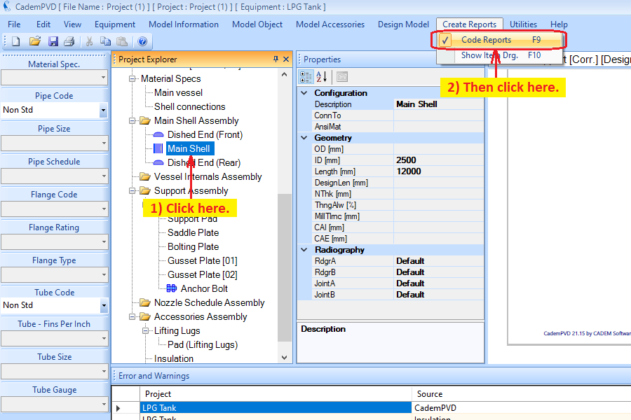
18. Click on the sub-entry ‘Main Shell’, and generate the design report for the Main Shell object by selecting the sub-menu ‘Code Reports’ from the top menu, ‘Create Reports’.
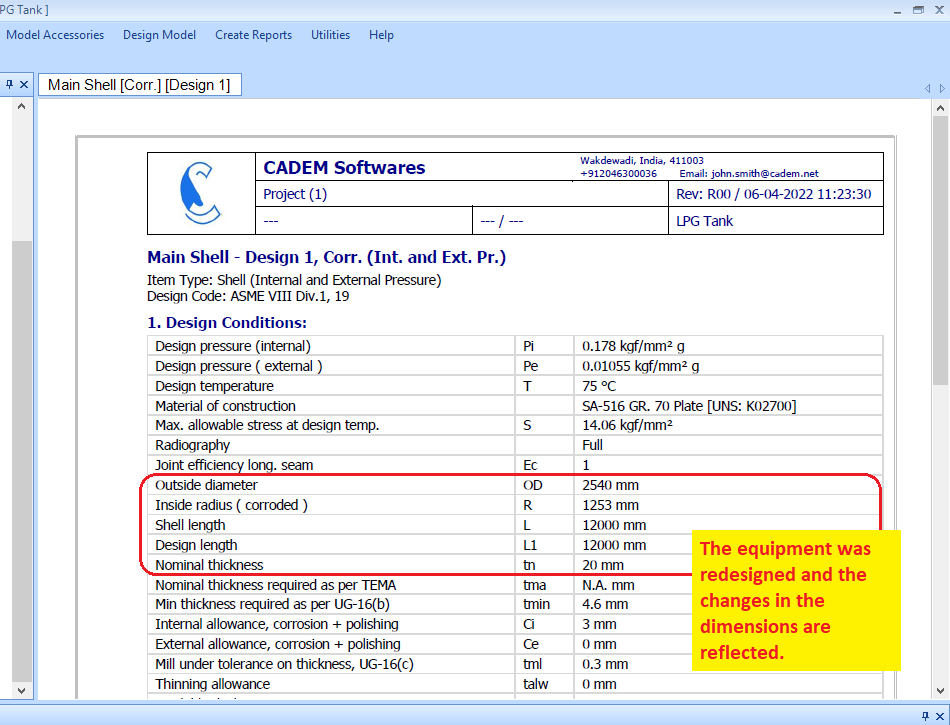
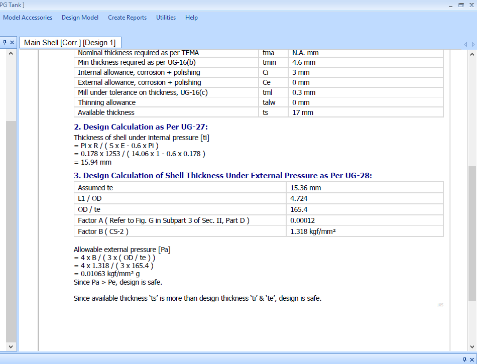
19. Now, generate the design report for the Left Side Dished End. As you can see, the changes in the Shell ID and Shell Length have been reflected in all other components.
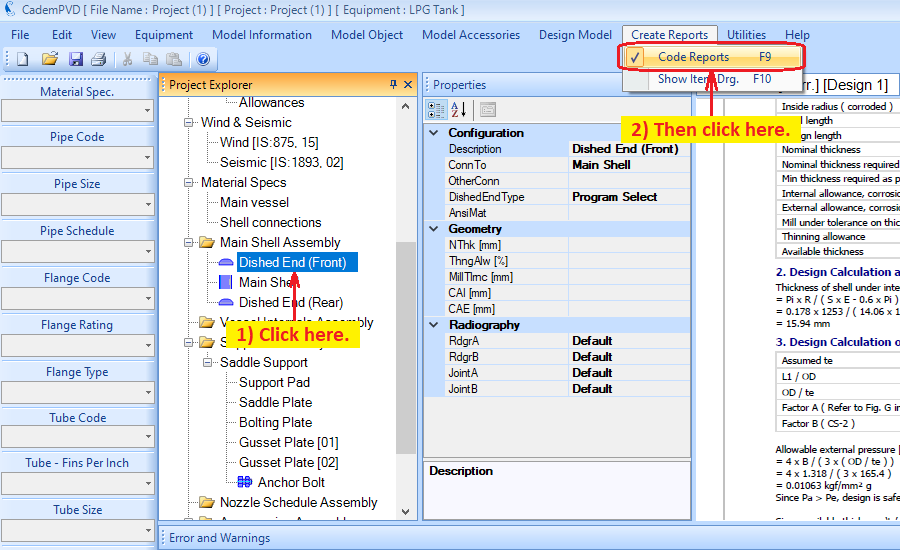
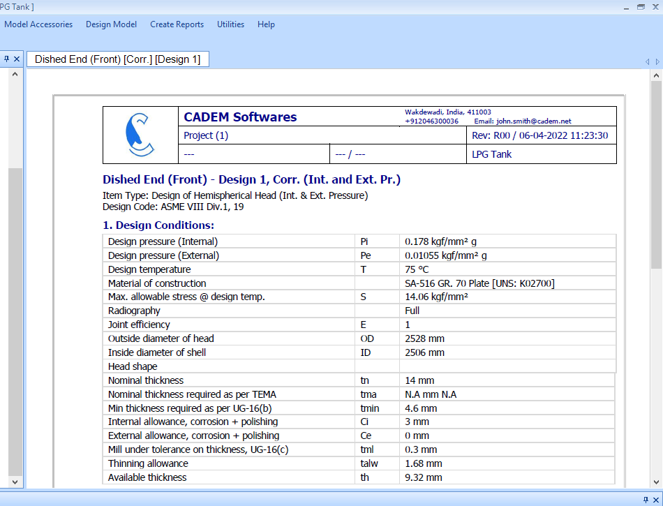
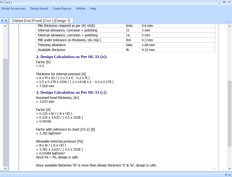
20. Proceed to generating the design report for the Saddle Support object.
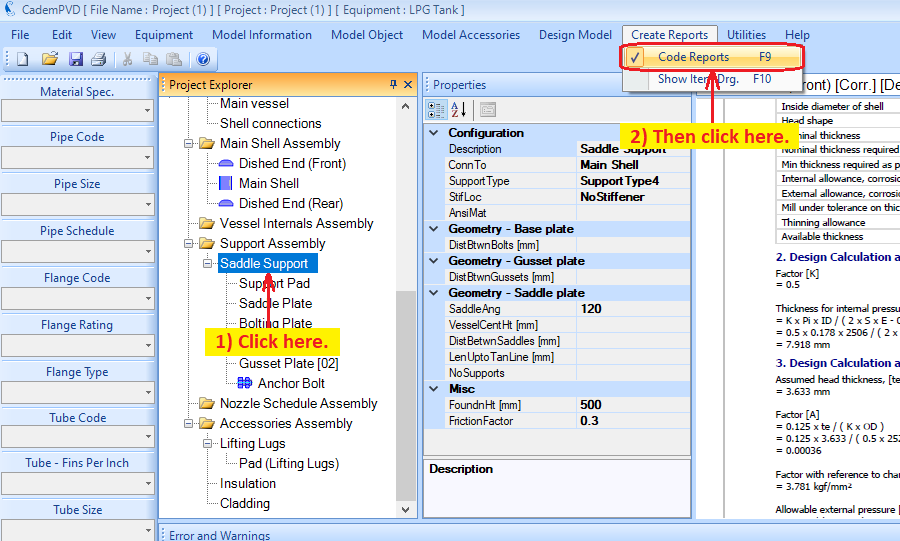
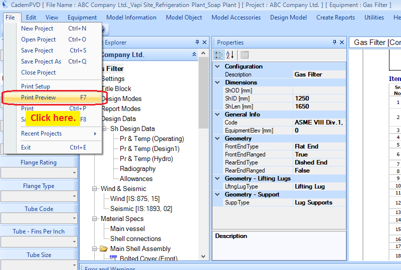
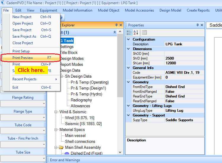
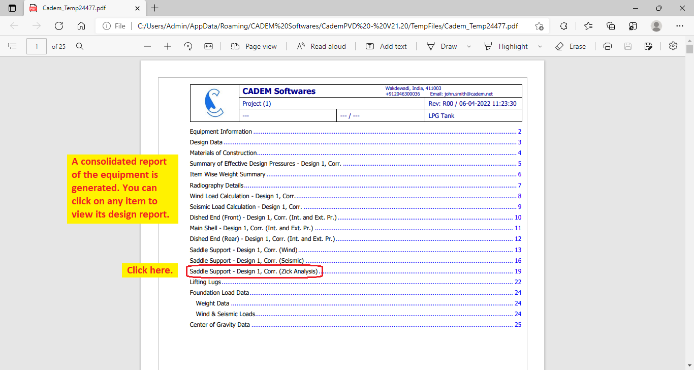
21. Select the submenu, 'Print Preview' under the 'File' menu, to generate a consolidated report of the equipment.
1A7D8RE9
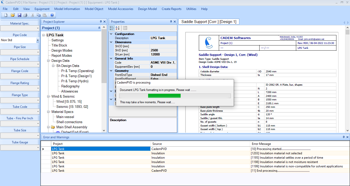
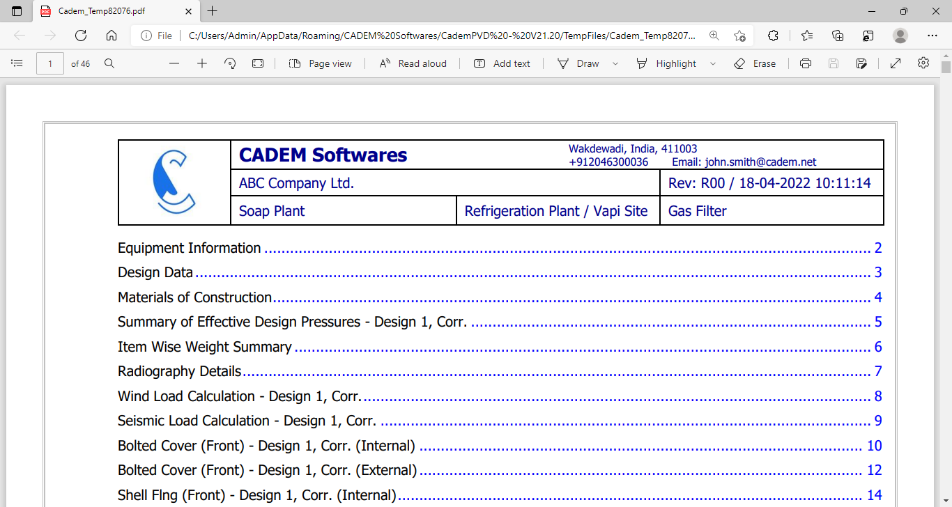
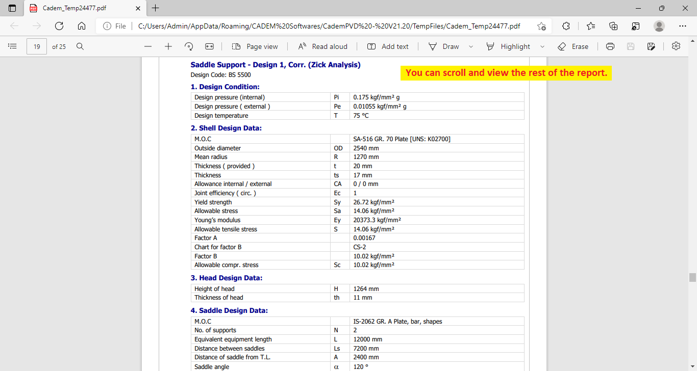
22. You can click on any item in the index, such as the Saddle Support object, and view its design.
PV-02 - Gas Filter
| Design Standard: ASME Section VIII Div. 1 | |||
| Pressure & Temperature | |||
| Operating | Design | Units | |
| Internal pressure | 12 | 15 | kg/cm2 |
| External pressure | 1.0546 | 1.0546 | kg/cm2 |
| Max. temperature | 100 | 120 | oC |
| Min. temperature | 20 | 10 | oC |
| Process media | Compressed Gas | - | |
| Process density | 10 | 12 | kg/m3 |
| Corrosion allowance | 3 | mm | |
| Polishing allowance | 0 | mm | |
| Materials of construction | |||
| Shell | SA-516-70 Plate | ||
| Head | SA-516-70 Plate | ||
| Manhole / body flange | SA-105 Frgs. | ||
| Nozzle | SA-106-B Smls. pipe | ||
| Flange | SA-105 Frgs. | ||
| Gasket | Spiral metal wound Graphite filled (S.S.) | ||
| Bolt | SA-193-B7 Bolting | ||
| Stiffener | SA-516-70 Plate | ||
| Reinforcement pad | SA-516-70 Plate | ||
| Support | IS-2062-A Plate | ||
| Anchor bolt | Commercial CS bolt | ||
| Lifting lug | IS-2062-A Plate | ||
You can watch this tutorial video on the design of a gas filter pressure vessel here: 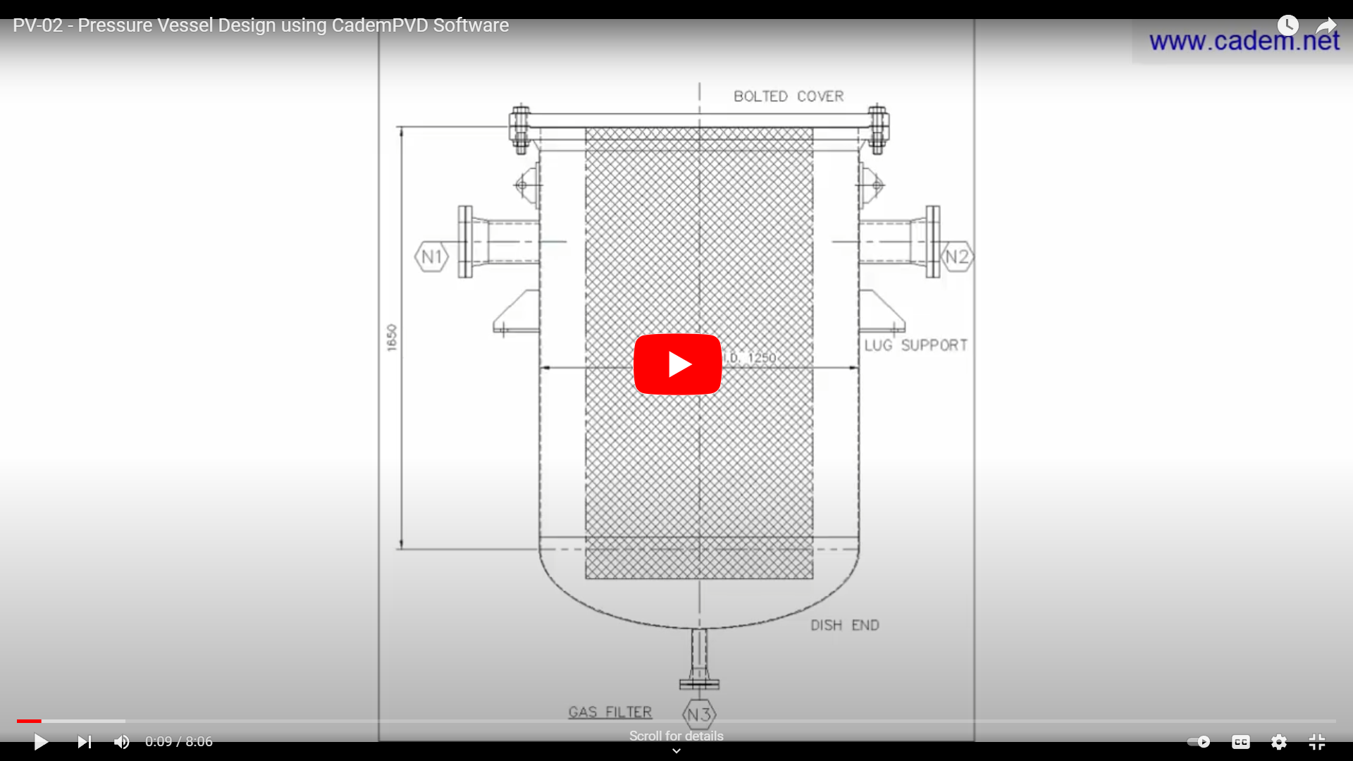
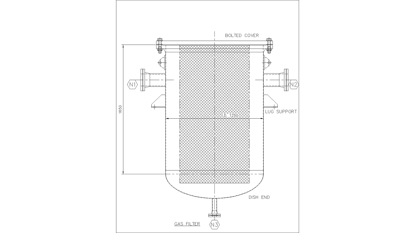
In this tutorial, we will design a simple vertical pressure vessel using CademPVD software. This pressure vessel has a top flat cover and a bottom dished end. The top cover is of a bolted type and is connected to the shell through a top body flange. The pressure vessel is provided with lug supports and lifting lugs.
Please refer to the above MDS for this equipment. Now let us add the equipment in the project by following the steps below.
1. Click on the 'Equipment' menu, and select the submenu, 'Pressure Vessel'.
2. Fill in the appropriate details that need to be filled in the displayed equipment configuration dialogue.
Since this vessel’s axis is vertical, the dialogue definitions, the front end and the rear end refer to the top end and the bottom end respectively. In case of a vessel with its axis horizontal on saddle supports, the front end and the rear end would refer to the left end and the right end respectively. Select 'True' for the 'FrontEndFlanged' entry. This will ensure that the top flat end is connected to the shell through a body or girth flange.
Click on the 'OK' button.
3. Enter the project details as shown.
4.Click on the entry 'Gas Filter', which by itself is a major definition entry, wherein the major configurational details or dimensional details are defined. Enter the contents in the 'Properties' Window as shown here below.
5. The next step is to input the Design Data information. Proceed to enter the operating condition data, consisting of the operating pressures - internal and external, and temperatures. Note that the pressure units are kgf/cm^2.
6. After entering the operating condition information, proceed to enter the design condition information consisting of the design pressures - internal and external, and temperatures.
7. If the user desires a hydrotest pressure greater than that required by the code, he can enter it in 'Pr & Temp (Hydro)'.
8. Select the applicable radiographic examination. We shall let the software choose the default radiography as required.
9. Enter the allowances information.
10. The user can edit the wind and seismic code parameters if required. The user can also change the wind and seismic code if required.
11. The next step is to add materials of construction for various components. You can define the materials of construction for the various material types in the common areas and thus save time required in defining materials for each individual component.
The definition of material is covered under the equipment subtree, 'Material Specs' in the 'Project Explorer'. Let us begin defining materials for the main vessel components. For this, select the 'Material Spec' combo box on the left side vertical menu strip and select from the list of predefined material specs or the data sets. The software user can update, add, or modify these data sets.
12. On selecting the material sets from the 'Material Spec.' combo box, suitable materials for the parts such as the shell, head, body flange, supports, lifting lugs etc. are automatically selected by the software. The user can edit the materials for the individual items after selecting a set from the ‘Material Spec.’ combo box. The user can also define his own custom material set.
Let us change the gasket material to a spiral wound one.
The next step is to define the materials for the nozzles or the connections.
13. This completes the material definitions. While following the above procedure, you have noticed that you have done minimum definitions or entered minimum inputs. The other entries have been left blank or empty and the software will select appropriate values for them. Let us now proceed to the design of the equipment.
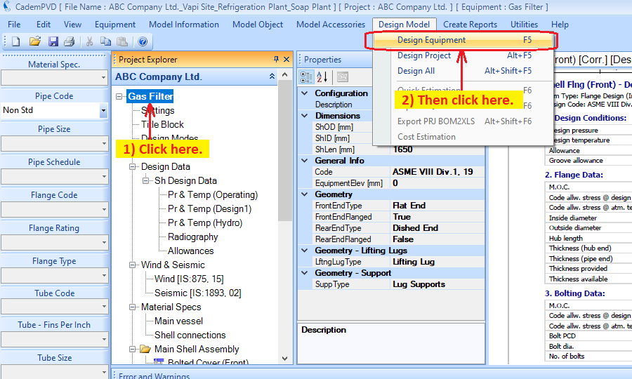
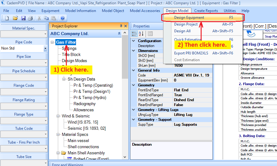
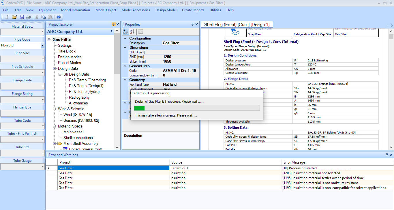
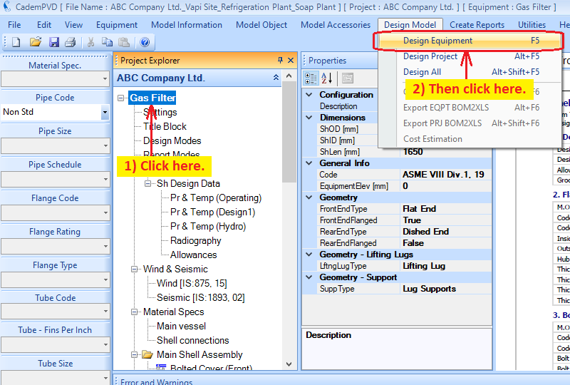
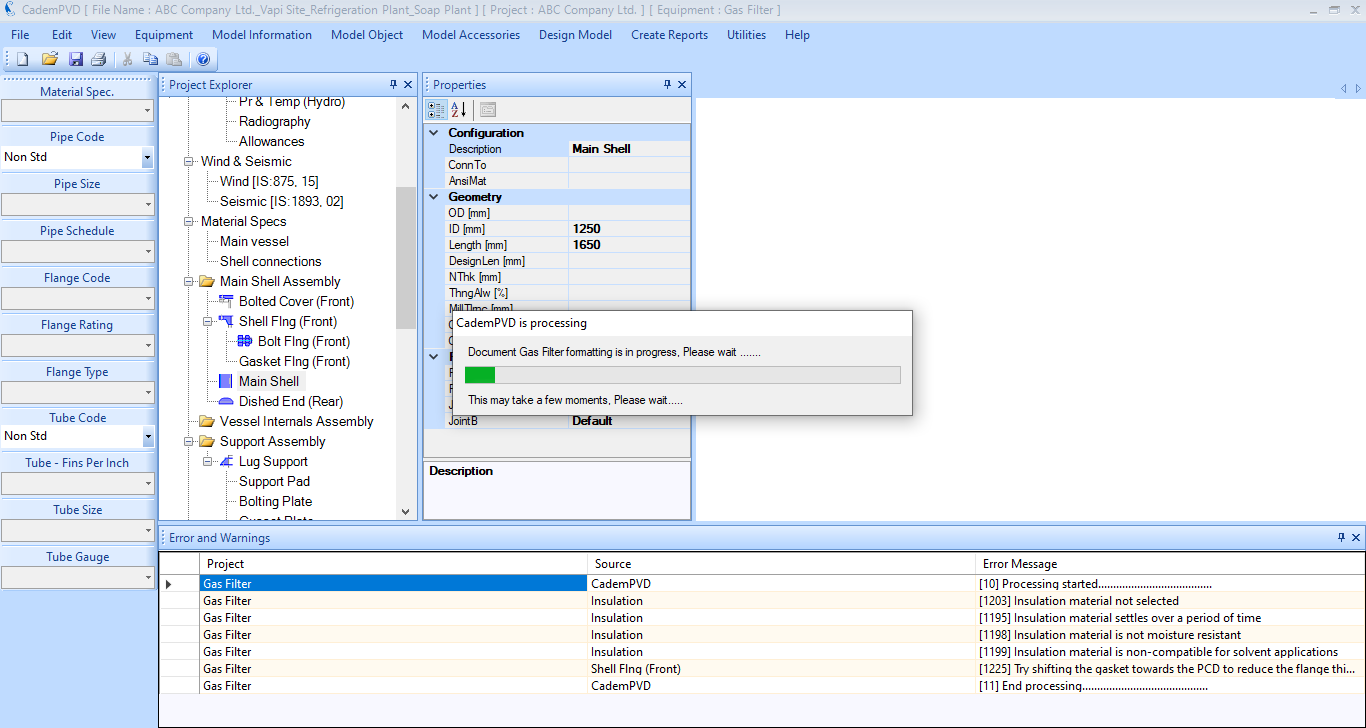
14. Click on the equipment tag to select the equipment to design in case there are multiple equipment in the project. Now, select the submenu 'Design Equipment' in the top menu, 'Design Model' to begin the design of the equipment.
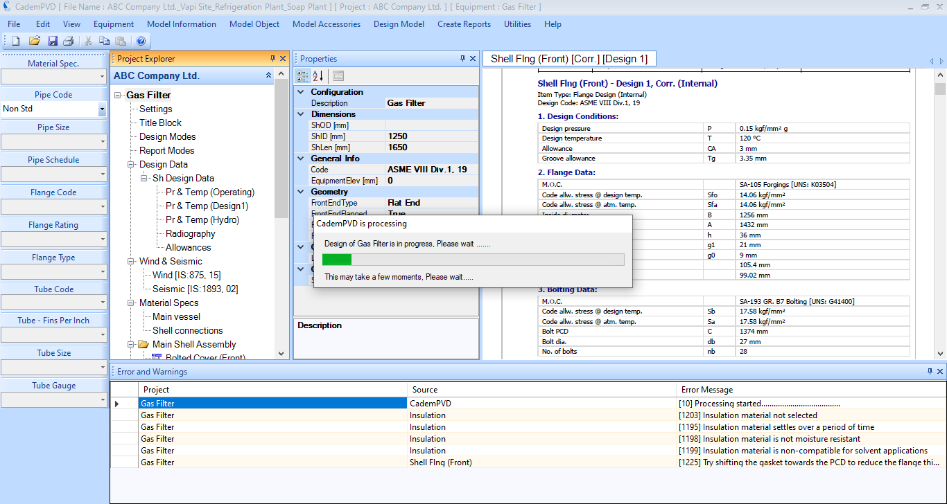
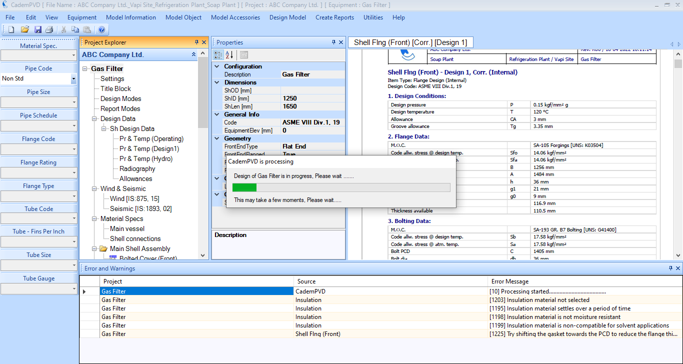
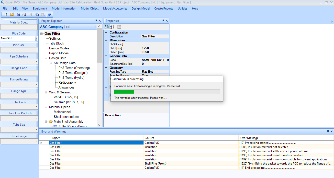
15. While the equipment is designed, any design warnings or errors that occur are displayed in the 'Errors and Warnings' window. The warnings are displayed in black colour and any severe errors displayed in red colour.
In the case of Warnings, the user can review them and take necessary corrective action, if required. While in the case of Errors, the user has to take necessary corrective action for the equipment design to proceed further.
You can notice that there are certain warnings only and there are no errors displayed in the 'Errors and Warnings' window.
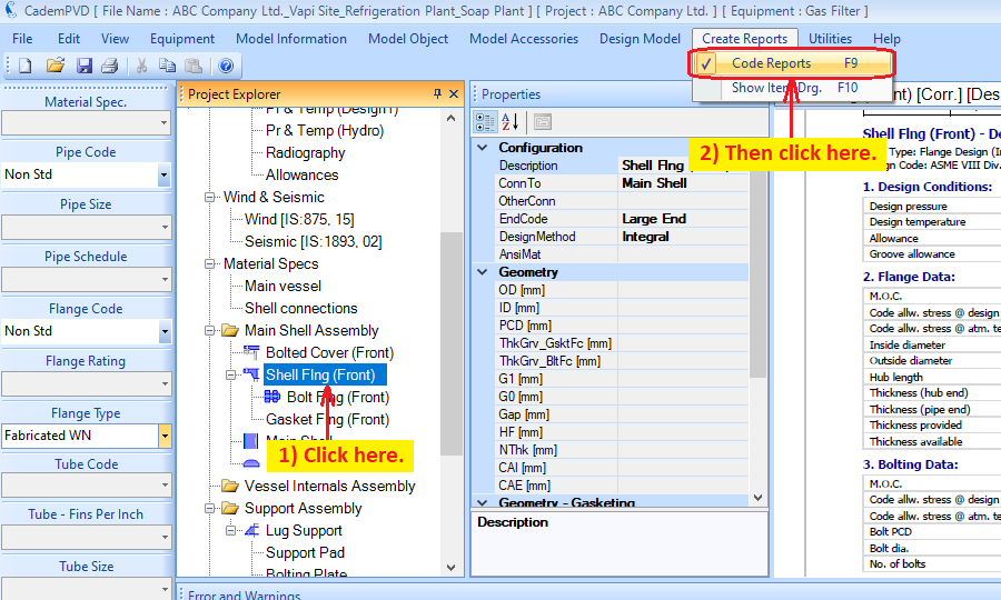
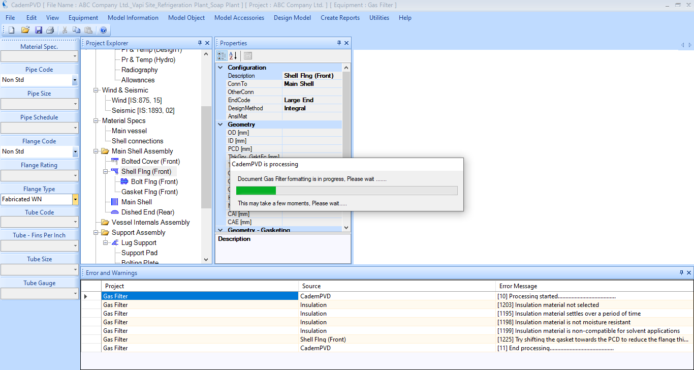
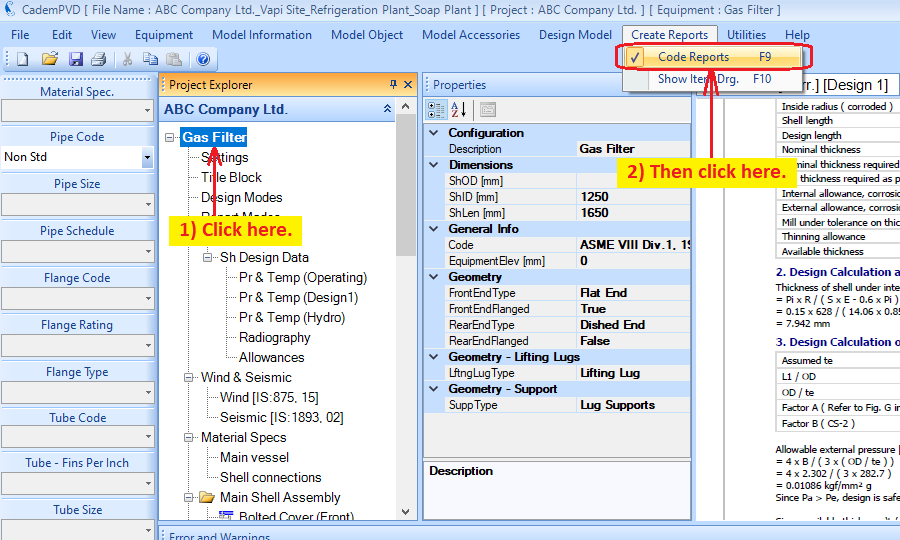
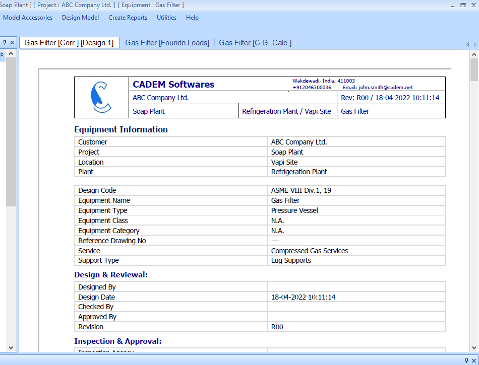
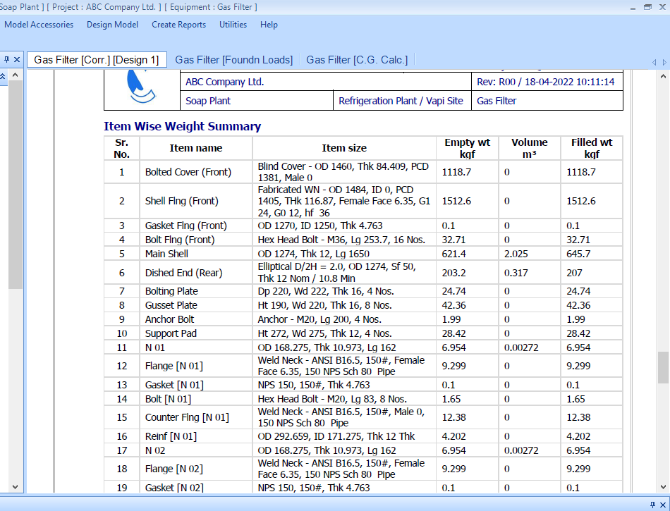
16. Let us proceed to see the design output for the top bolted cover item, 'Bolted Cover (Front)'. The steps to depict the design output for this item as shown in the following screen.
17. Similarly, the report for the top body flange, the 'Shell Flng (Front)' object can be generated.
18. The 'Shell Flng (Front)' just designed shows the Bolt Diameter as 33 mm and the Number of Bolts as 20. Also our selection for the Flange material is plate material.
19. Now, let us change the flange configuration to Forged SA 105 of type WNRF.
20. Similarly, update the material for the 'BodyFlngCvr' object.
21. Now, click on the 'Shell Flng (Front)' object and update the 'Flange Type' and 'DesignMethod' property as indicated.
22. Select the submenu 'Design Equipment' in the top menu, 'Design Model' to re-design the equipment and thereafter check the 'Shell Flng (Front)' design output.
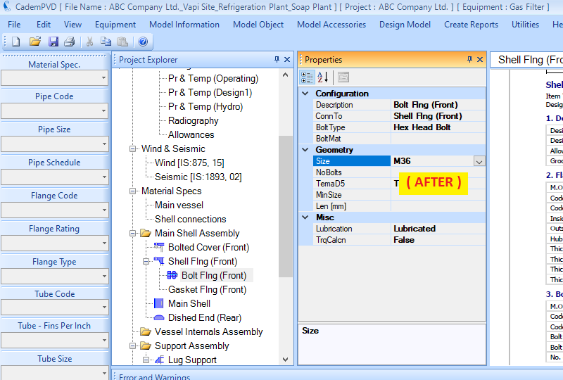
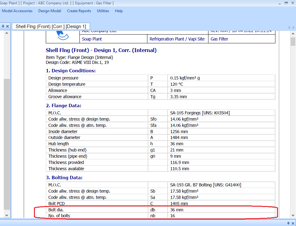
23. The top body flange report shows the optimum design which uses 28 bolts of size 27 mm. Let’s override this and proceed to setting the bolt size to M36, and redesigning the equipment.
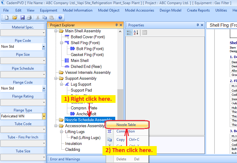
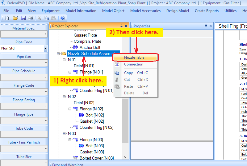
24. The top body flange design using M36 bolts is as shown above. After designing the overall equipment, we now proceed to adding nozzles for the equipment.
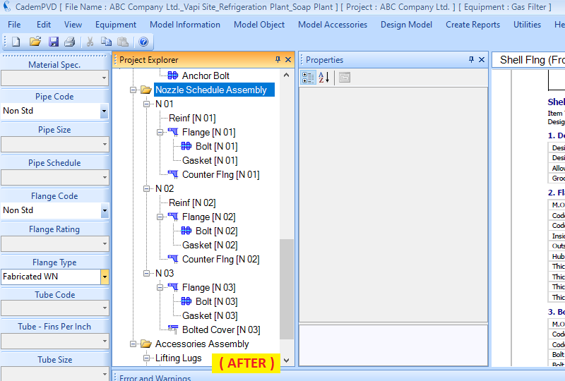
25. After entering the details as shown in the above 'Nozzle Schedule' dialog, click on the 'OK' button to update the model.
26. Select the sub-menu 'Design Equipment' in the top menu, 'Design Model' to re-design the equipment.
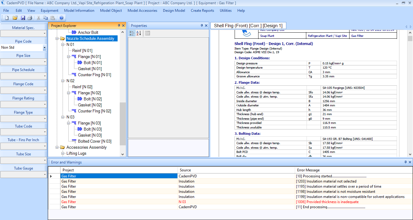
27. The 'Errors and Warnings' window is displaying an error in red colour which is a severe error. The design cannot proceed further unless we rectify this error. The error has occurred in the the nozzle neck of 'N 03' , which says that the provided neck thickness is inadequate. Rectify this by selecting a higher schedule for the nozzle, 'N 03'.
28. Proceed to redesign the equipment.
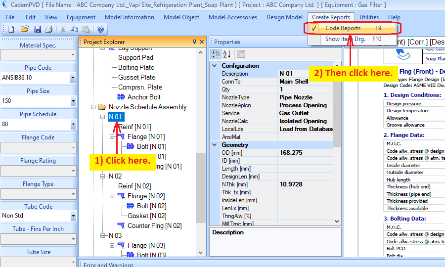
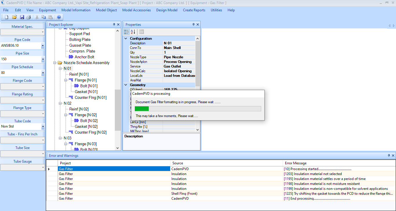
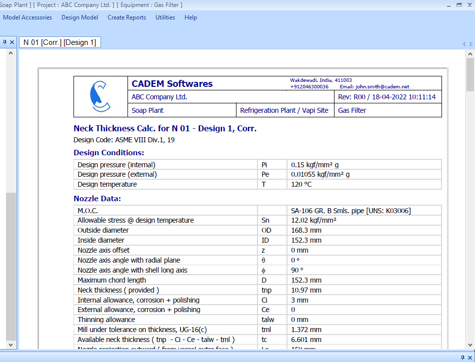
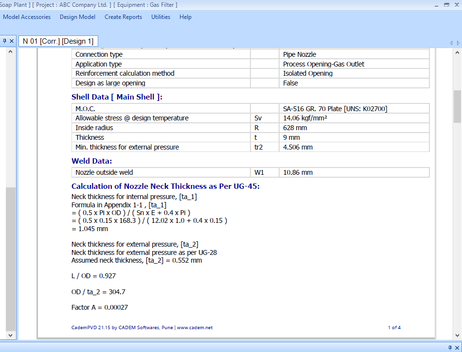
29. After redesigning the equipment, no more errors are displayed in the 'Errors and Warnings' window. Generate the design report for the nozzle N-01.
30. You can click on any item or object in the Equipment Tree and see its Design Report by selecting the submenu 'Code Report', from the top menu, 'Create Report'.
You can view the design report in the pdf format by selecting the submenu, ‘Print Preview’ under the 'File' menu.
This completes the tutorial demonstrating the design of an ASME Pressure Vessel in our software, CademPVD. Thank you.

