CademPVD Software is an intelligent software for the mechanical design of process equipment using minimum inputs. Click here to know more.
Reaction Vessel ( Reactor ) with Agitator Shaft Design Software
How to design a reaction vessel with an agitator shaft?
On this webpage, you will find a number of tutorials on the design of reaction vessels with agitator shafts, using CademPVD software.
| Index | |
Reactor RV-01
Reaction Vessel Reactor Agitator Shaft Design Calculations ASME Section VIII Division 1 ASME Section 8 Division 1 EEUA Report
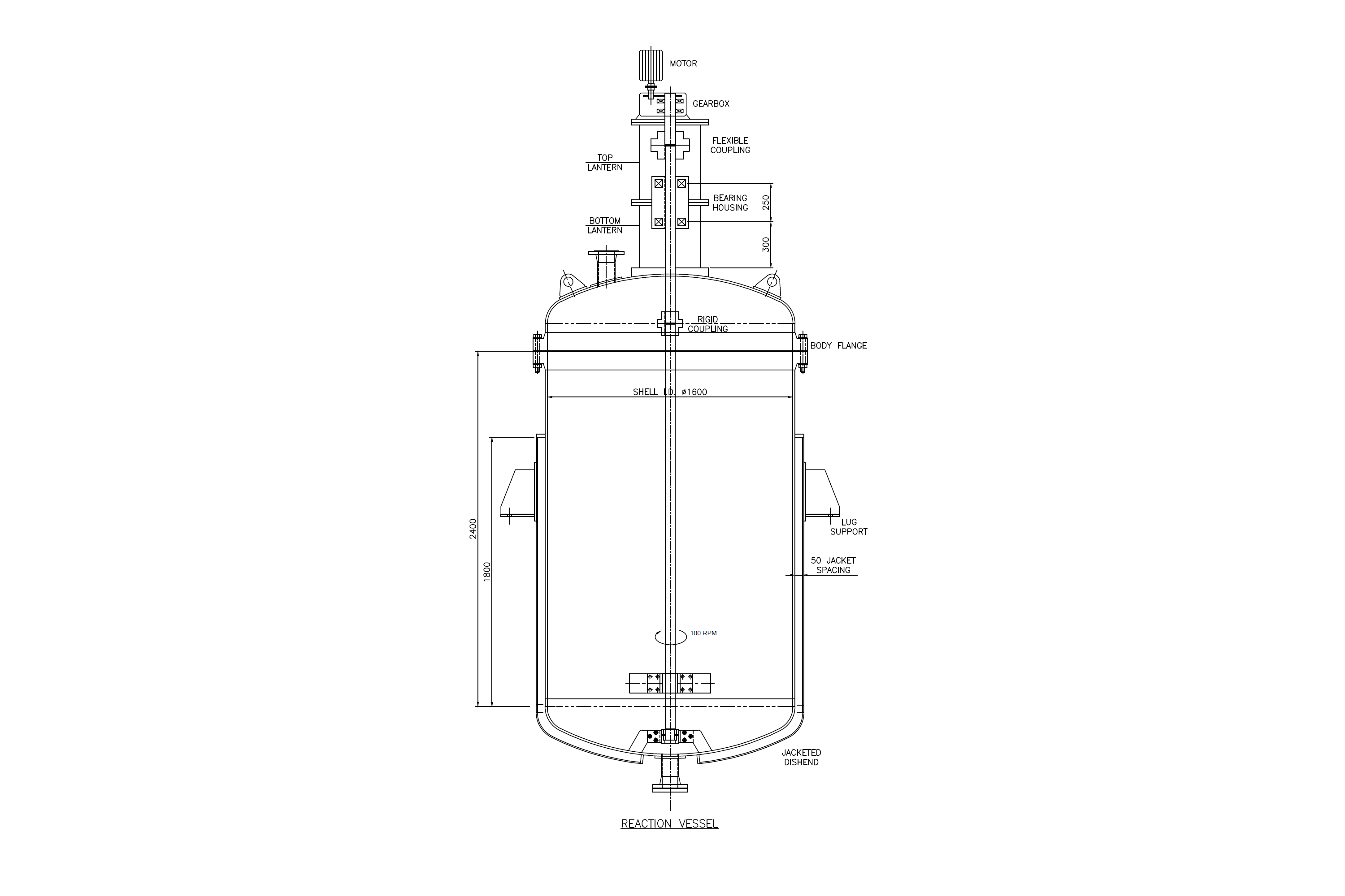
| Design Standard: ASME Section VIII Div. 1 | |||||
| Pressure & Temperature | Shell Side | Jacket Side | |||
| Operating | Design | Operating | Design | Units | |
| Internal pressure | 6 | 8 | 4 | 5 | kg/cm2 |
| External pressure | 1.0546 | 1.0546 | 1.0546 | 1.0546 | kg/cm2 |
| Max. temperature | 120 | 180 | 150 | 200 | oC |
| Min. temperature | 18 | 10 | 18 | 10 | oC |
| Process media | Chemical 1 | Steam | - | ||
| Process density | 980 | 1.5 | kg/m3 | ||
| Radiography & allowances | Shell | Head | Shell | Head | Units |
| Radiography | Full | Full | Full | Full | - |
| Corrosion allowance | - | - | mm | ||
| Materials of construction | |||||
| Shell side | Jacket side | ||||
| Shell / Jacket shell | SA-240 316 Plate | SA-240 304 Plate | |||
| Head | SA-240 316 Plate | SA-240 304 Plate | |||
| Manhole / body flange | SA-182 F316 Frgs. | - | |||
| Nozzle | SA-312 TP316 Smls.pipe | SA-312 TP304 Smls.pipe | |||
| Flange | SA-182 F316 Frgs. | SA-182 F304 Frgs. | |||
| Gasket | Spiral metal wound CAF filled (S.S.) | Spiral metal wound CAF filled (S.S.) | |||
| Bolt | SA-193 B7 Bolting | SA-193 B7 Bolting | |||
| Stiffener | SA-240 316 Plate | SA-240 304 Plate | |||
| Reinforcement pad | SA-240 316 Plate | SA-240 304 Plate | |||
| Support & lifting lug | IS-2062 A Plate | ||||
| Anchor bolt | Commercial CS bolt | ||||
| Jacket closure | - | SA-240 304 Plate | |||
| Agitator Shaft Data | Blade data | ||||
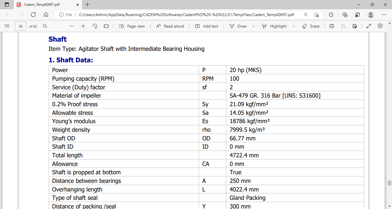
| Power | 20 HP | No. of blades / hub | 2 | ||
| Duty | Heavy | Radius | 800 mm | ||
| R.P.M. | 100 | Width | 50 mm | ||
| Material | 18/8 Cr-Ni steel | Angle | 45 deg | ||
| Shaft type | Intermediate housing | Thickness | 16 mm | ||
| Daily usage | 8 Hours | ||||
| Expected life | 4 Years | ||||
| Allowable deflection | 0.5 mm (at seal) | ||||
You can watch this tutorial video on the design of a reaction vessel with an agitator shaft here: 
1.In this example, we will see how to design the above Reaction Vessel with an Agitator Shaft using CademPVD software.
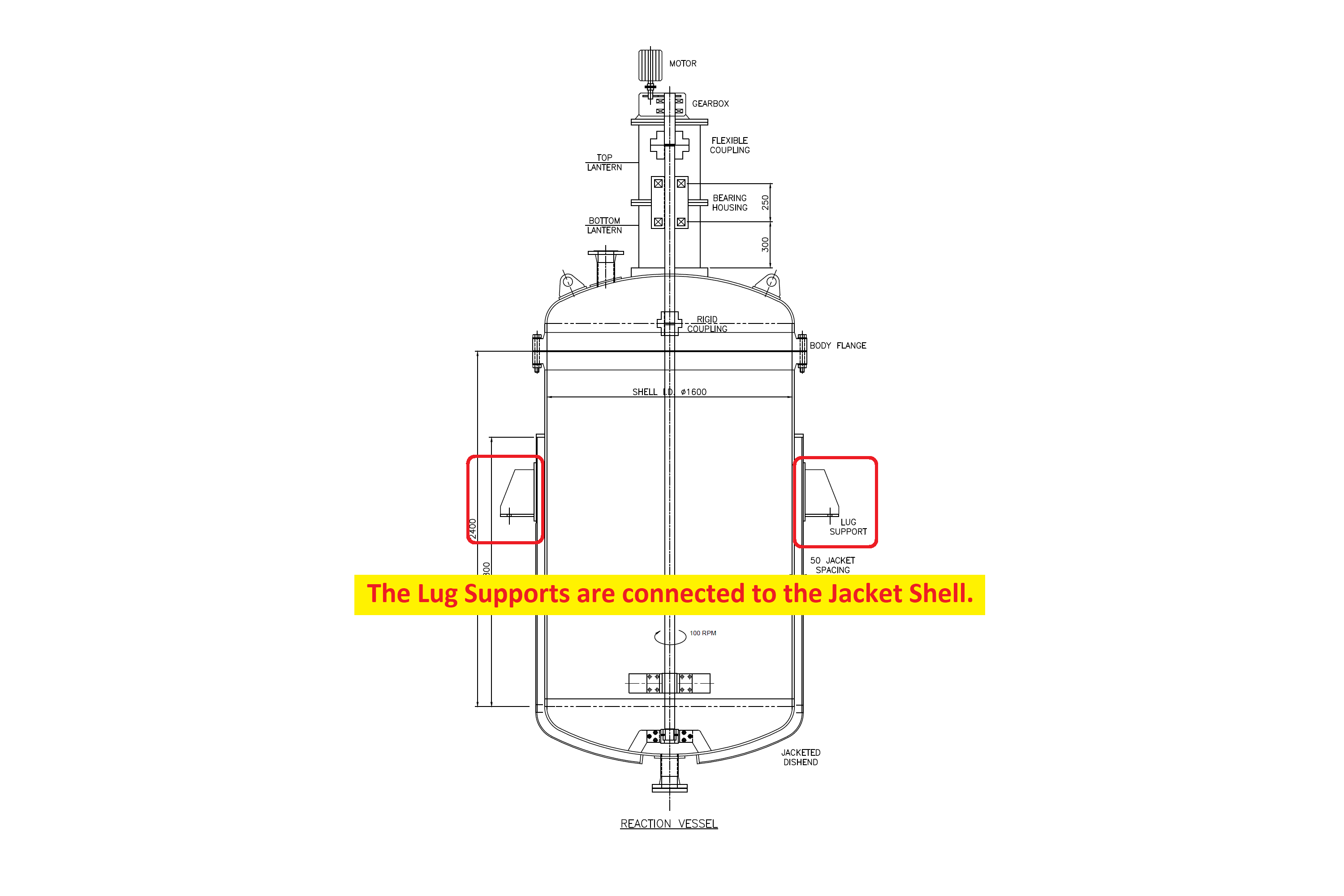
Its jacketing is of a plain shell type, partially covering the main shell and extending on to the bottom dished end. It has an agitator, with 20 HP power and the Agitator Shaft RPM is 100. All the components in contact with the internal process liquid are of SS 316 and the jacketing is of SS 304.
Please refer to the above MDS for this equipment. Now let us add the equipment in the project by following the steps below.
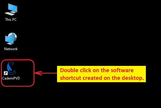
2.Open CademPVD by double clicking on the software shortcut on your desktop.
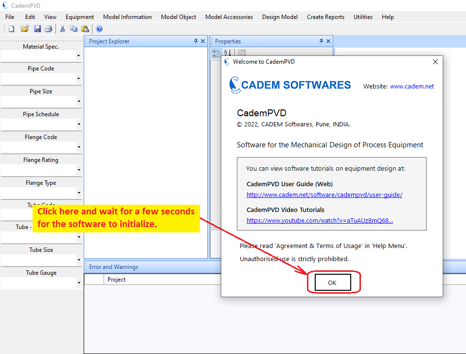
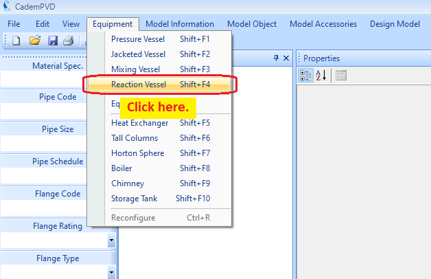
3.Click on the 'Equipment' menu, and select the submenu, 'Reaction Vessel'.
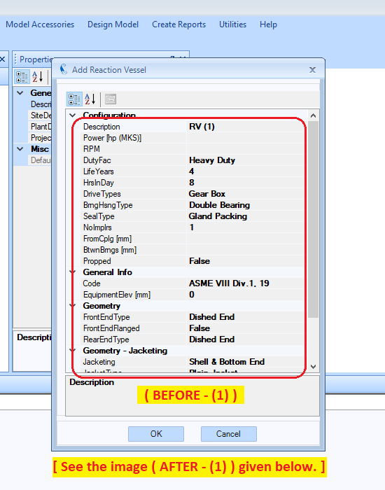
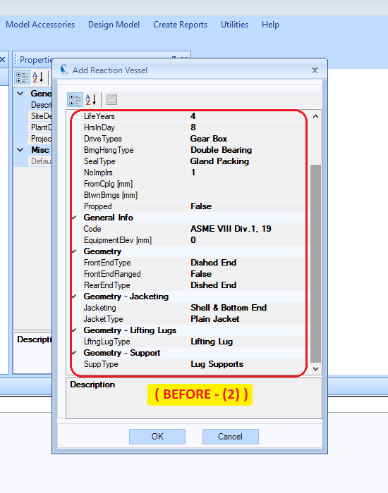
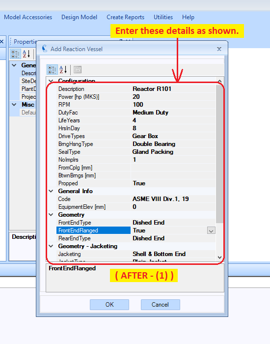
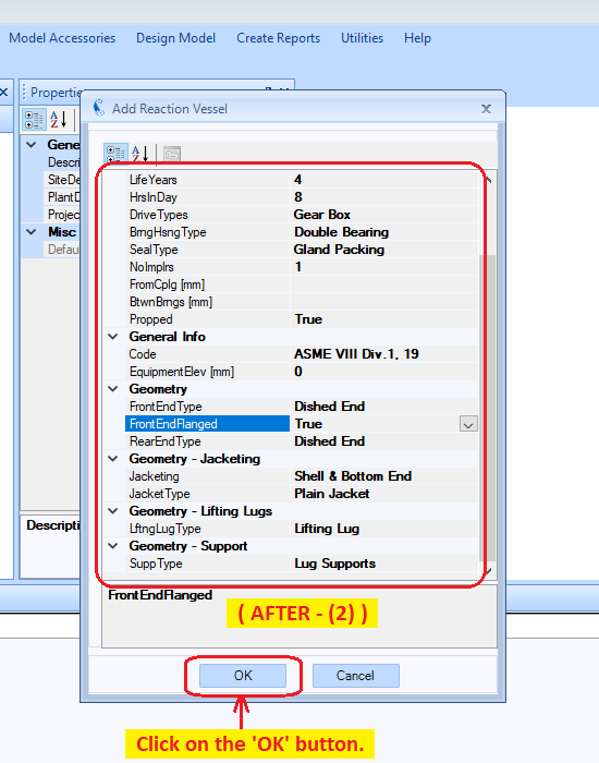
4.Fill in the appropriate details that need to be filled in the displayed equipment configuration dialogue.
The field entries, “LifeYears” and “HrsInDay” are the expected working years and the daily hours of operations respectively. These two inputs together determine the million number of revolutions to which the shaft supporting bearings are subjected. These revolutions along with the loads, are used in the appropriate selection of the bearings.
We are designing a shaft with a single impeller and hence, the field entry “NoImplrs” is set to 1.
Consider the field entry, “Propped”. In case the shaft is provided with an additional guiding bush support near the bottom end, this field should be set to true. The rest of the entries in this dialog are self explanatory. Now, click on dialog’s button 'OK'.
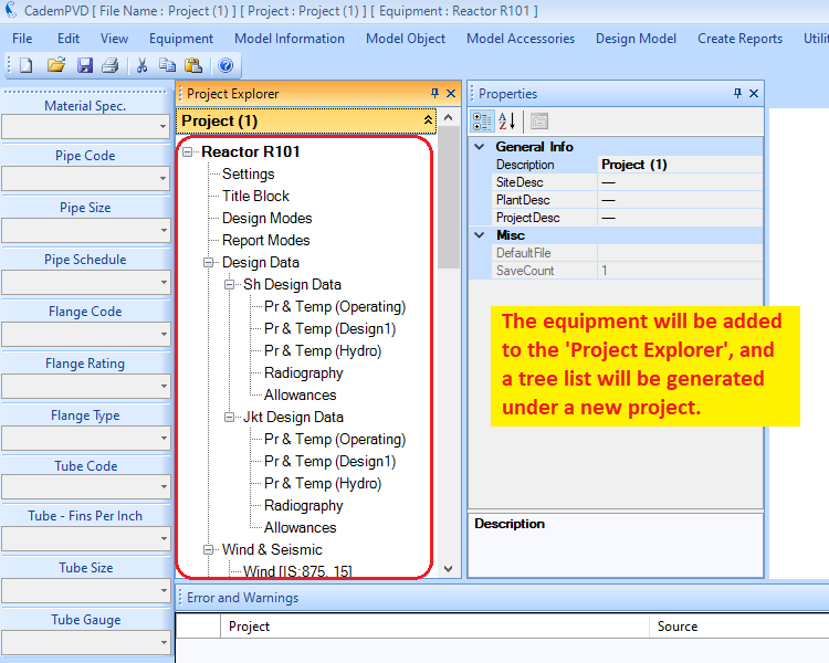
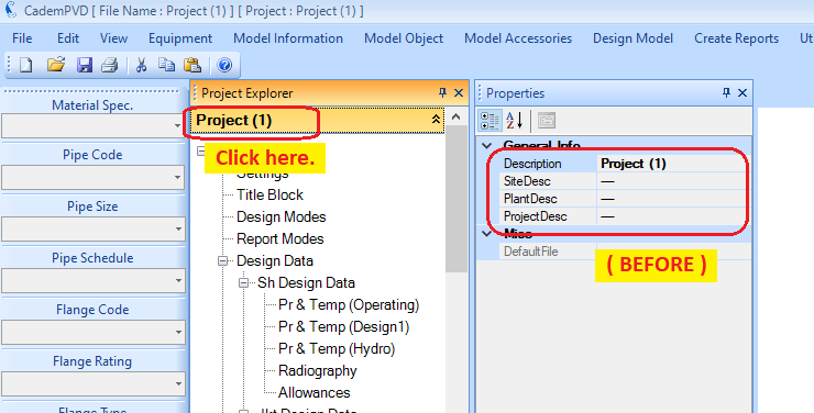
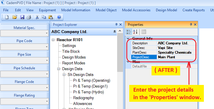
5.Update the project details as shown.
6.Click on the entry, 'Reactor R101' and update its contents in the 'Properties' window.
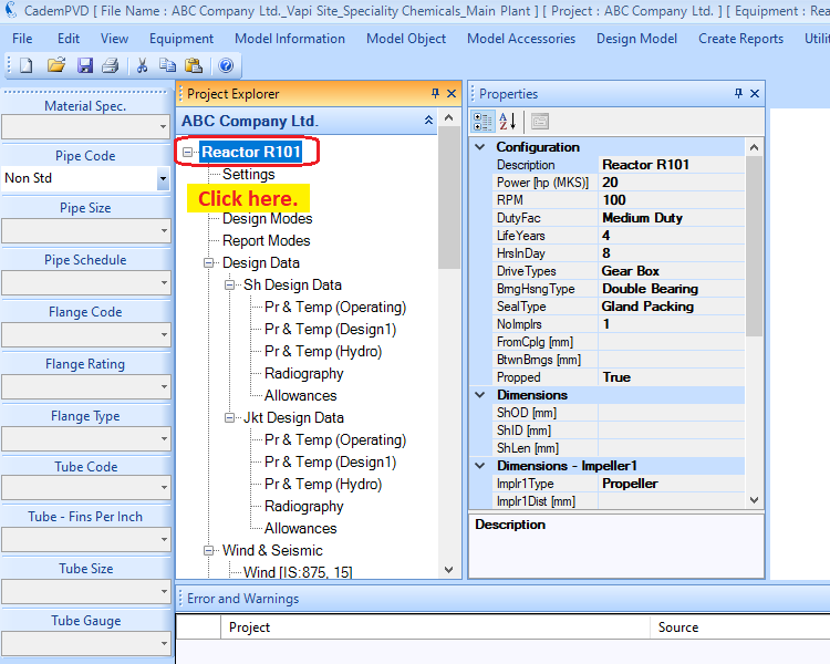
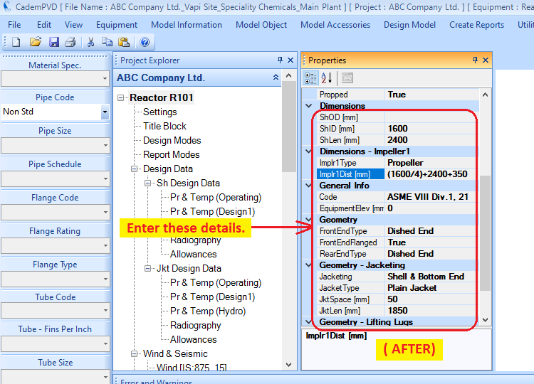
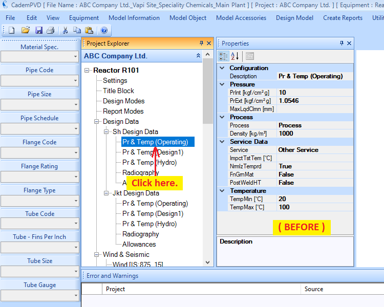
7. The next step is to input the design data information. For this, locate the tree node entry, 'Design Data', and then the subentry 'Sh Design Data' within. For the reaction vessel, one has to enter shell side and jacket side design data.
First enter the shell side operating data. Note that the pressure units are kgf/cm^2.
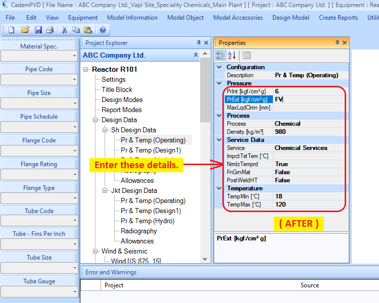
8. The next step is to update the design condition information.
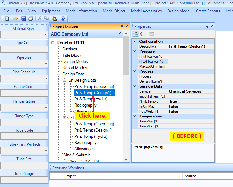
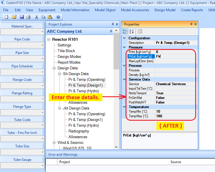
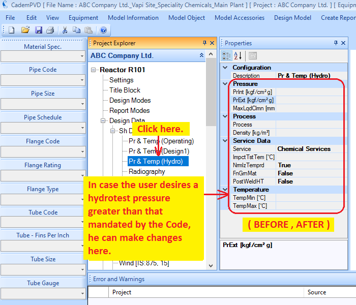
9. The user can edit the hydrotest design data, if required.
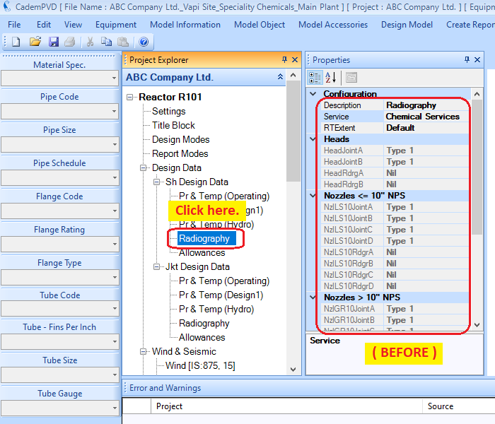
10. Select the applicable radiographic examination.
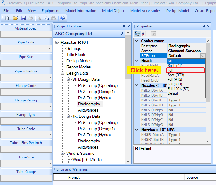
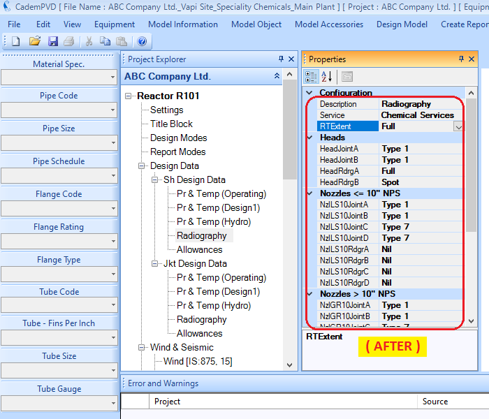
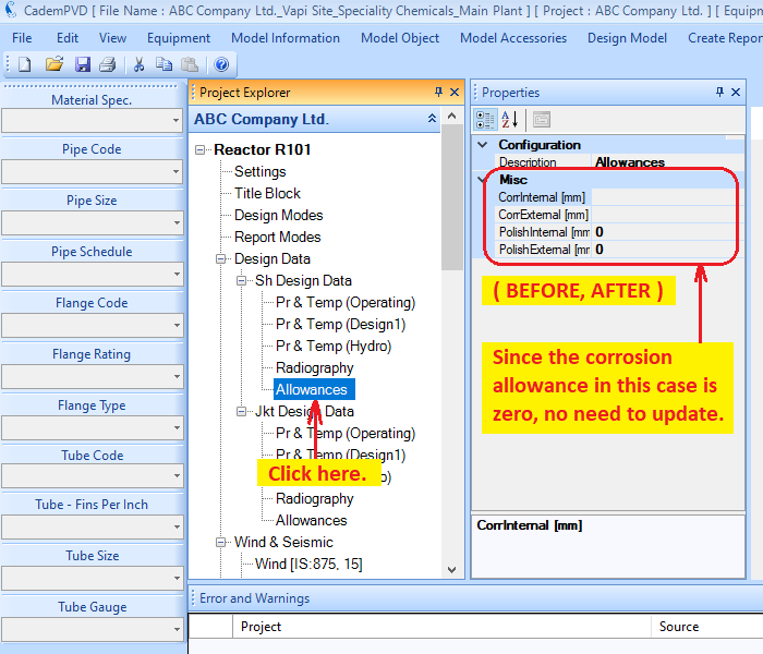
11. Click on the subentry, 'Allowances'. In our case, since the corrosion allowance is zero, no need to make any changes here.
12. This process completes the definition of the shell side design data information. Now proceed to defining the jacket side design data, which you can update in the subtree entries under 'Jkt Design Data'.
First, fill in the jacket operating condition data as shown.
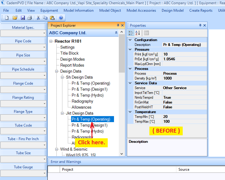
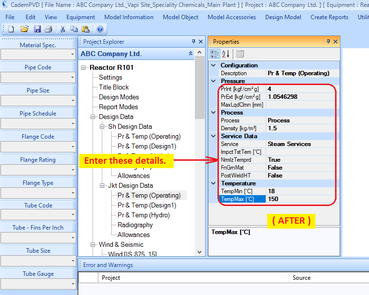
13. Next, fill in the jacket design condition data as shown here below:
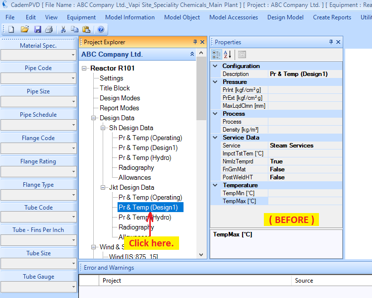
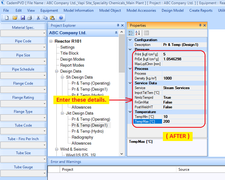
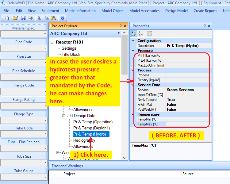
14. If the user desires a hydrotest pressure greater than that required by the code, he can update it in 'Pr & Temp (Hydro)' parameters. In our case, we aren't changing the hydrotest parameters.
15. Select the applicable radiographic examination.
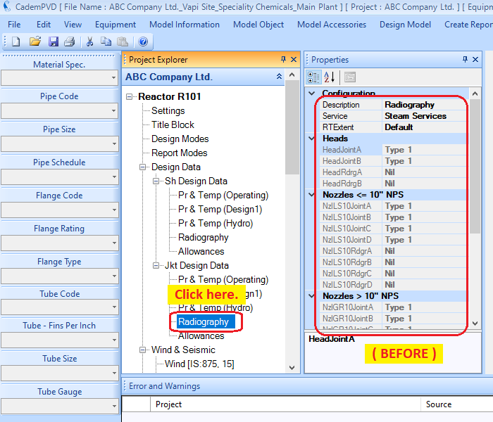
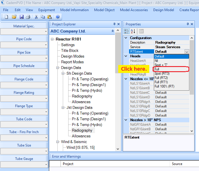
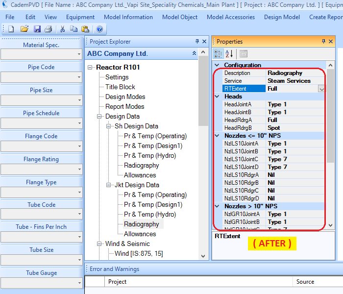
16. Click on the subtree entry, 'Allowances'. Since we are not providing any corrosion allowance, no updating is required over here.
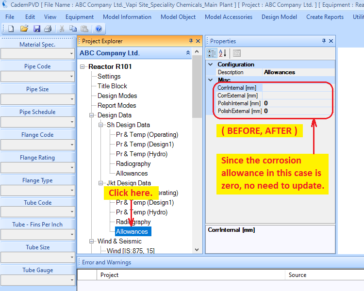
17. The user can edit the wind and seismic code parameters if required. The user can also change the wind and seismic code if required.
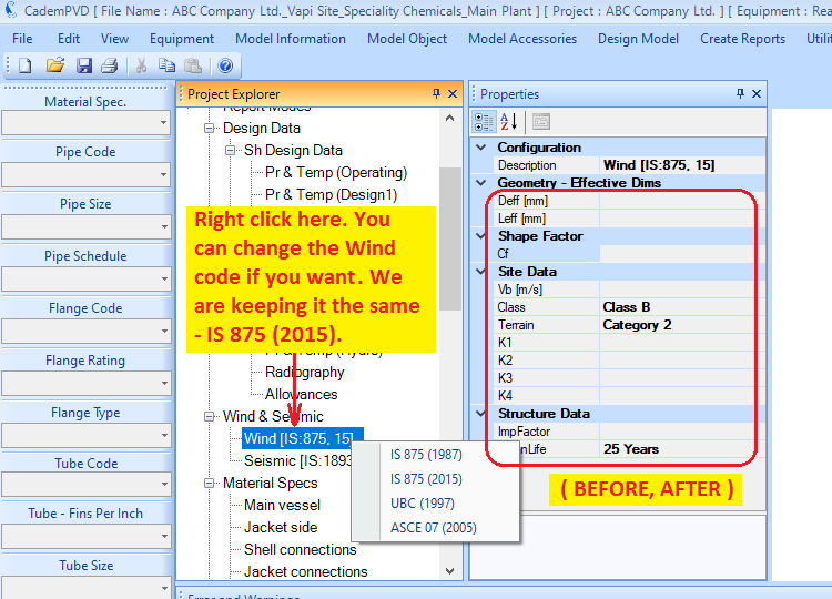
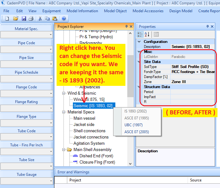
18. The next step is to apply the materials of construction for the various components. You can define this in the common areas, thus saving the time required in defining the material for each individual component. The definition of the materials is covered under the equipment subtree, 'Material Specs', in the Project Explorer. The 'Material Spec' combo box on the left side vertical menu strip lists predefined material specs or data sets.
On selecting the material set from Material Specs, suitable materials for parts such as body flange, shell, head, support, lifting lug etc. are automatically selected by the software. The user can edit materials for individual items after selecting a set from ‘Material Spec.’ The user can also define his own custom material set.
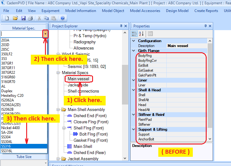
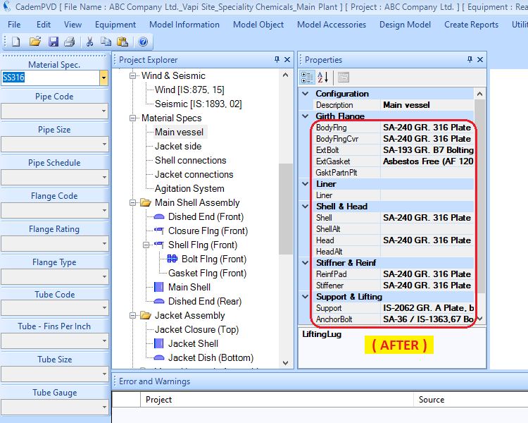
19. Let us choose a spiral wound material for the external gasket for the main vessel and the jacket side.
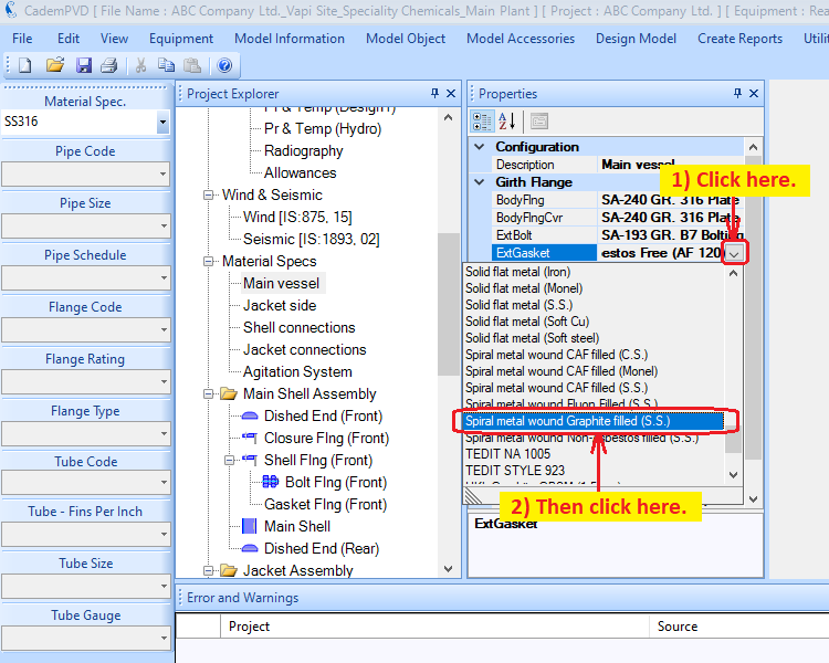
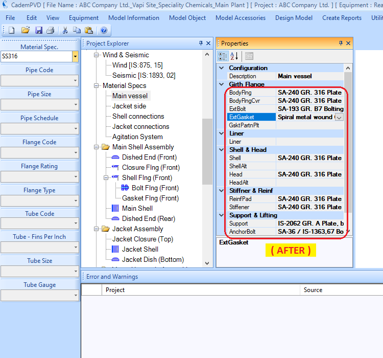
20. Select the Material Spec, 'SS304' for the Jacket Side.
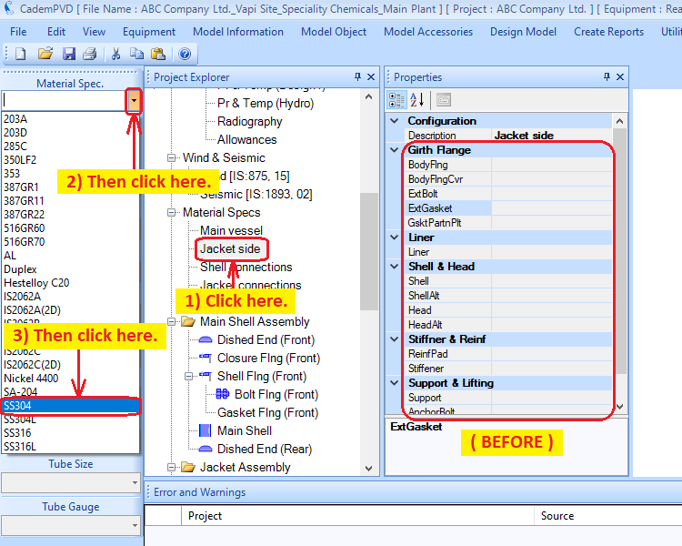
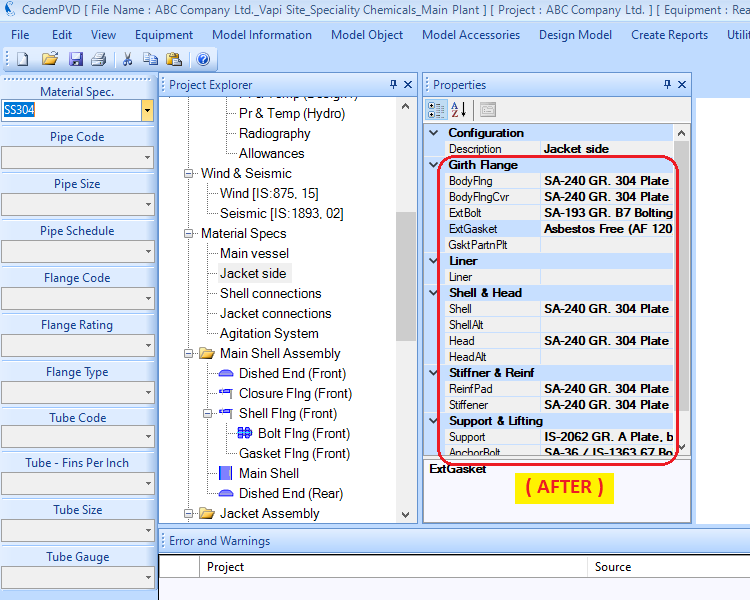
21. Similarly, you can now proceed to select the materials for the Shell Connections, Jacket Connections and the Agitator System. Choose the Material Specs 'SS316', 'SS304' and 'SS316' for the Shell Connections, Jacket Connections and the Agitator System respectively.
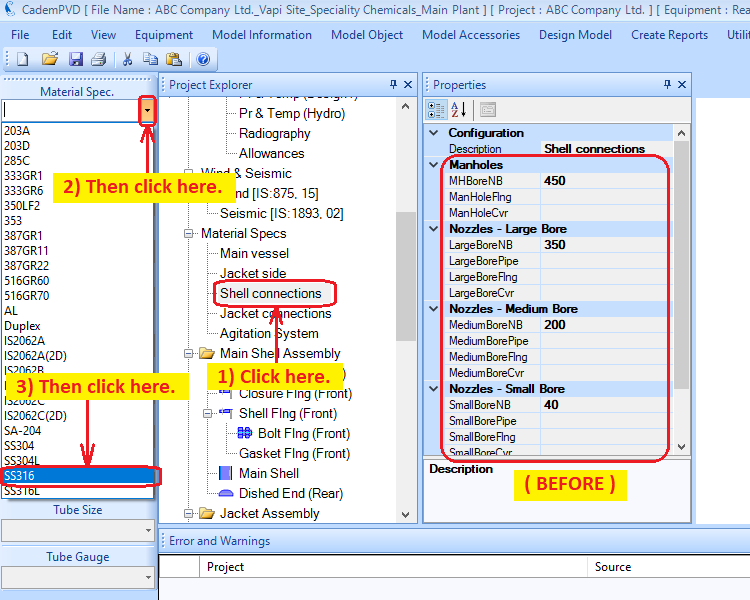
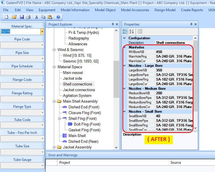
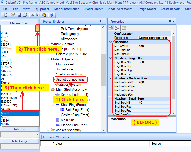
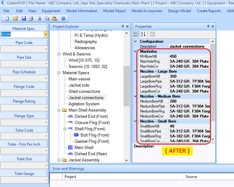
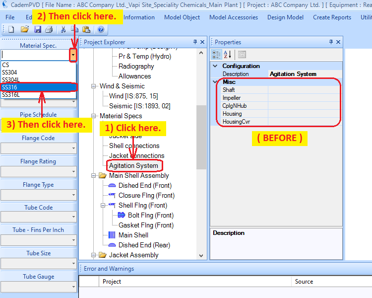
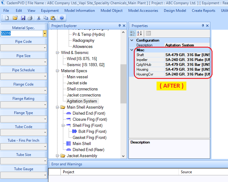
This completes the process of definition of materials for the various components.
Thus, in following the entire above process, we have defined the equipment configuration, its overall dimensions, its design data like pressures, temperatures under various conditions, radiography, allowances and materials for the various components.
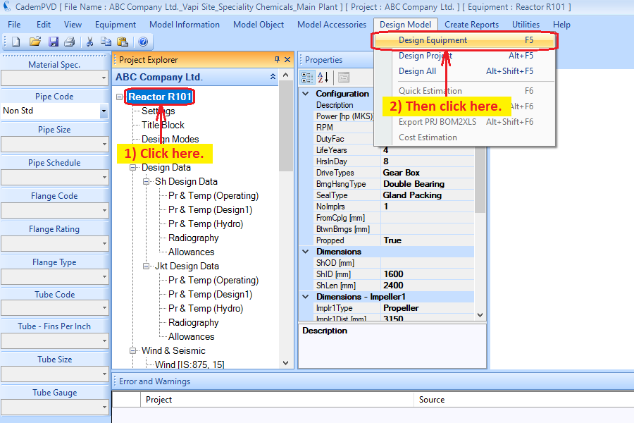
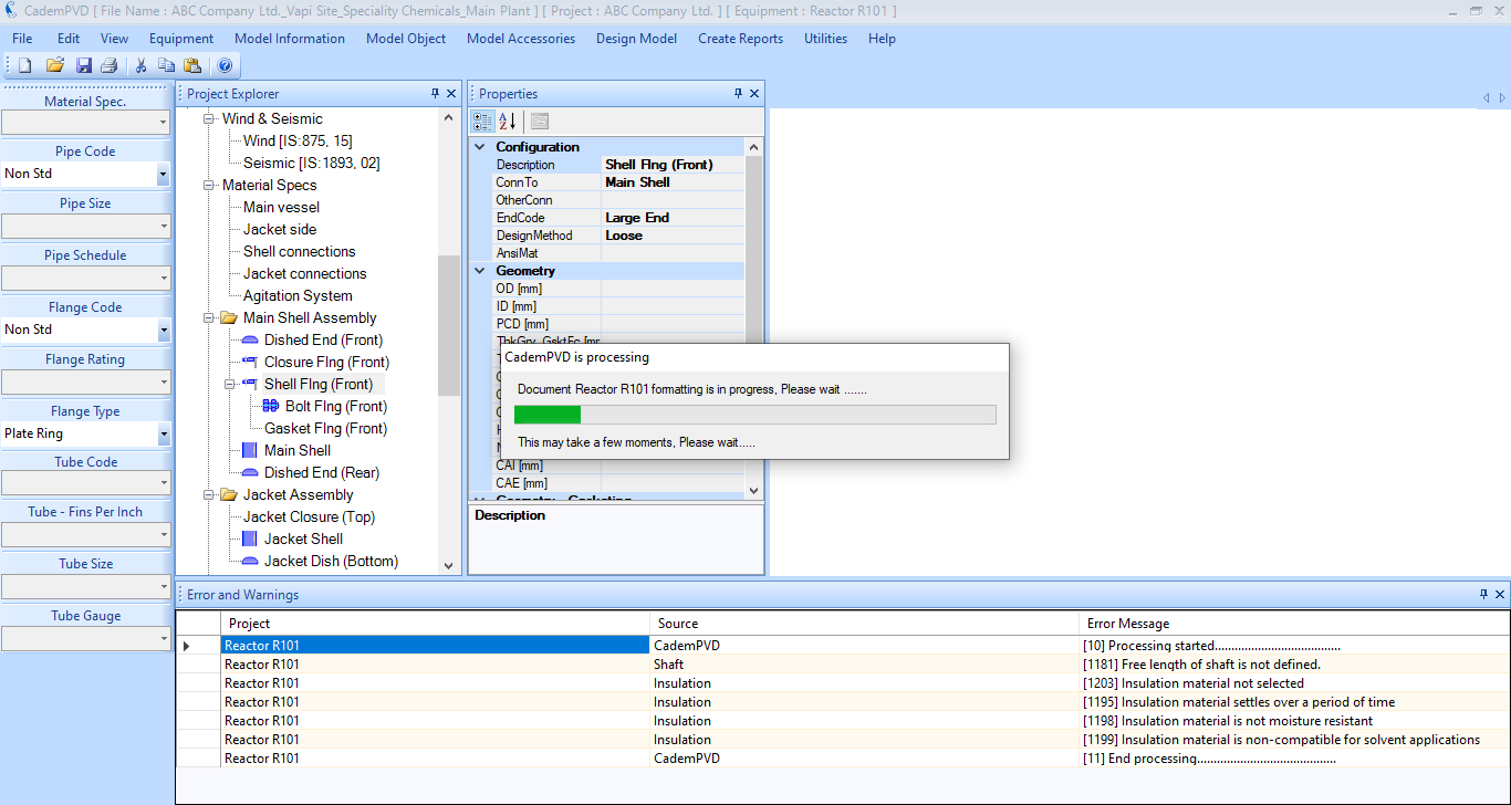
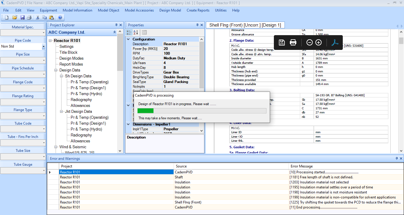
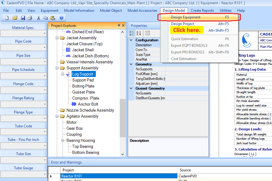
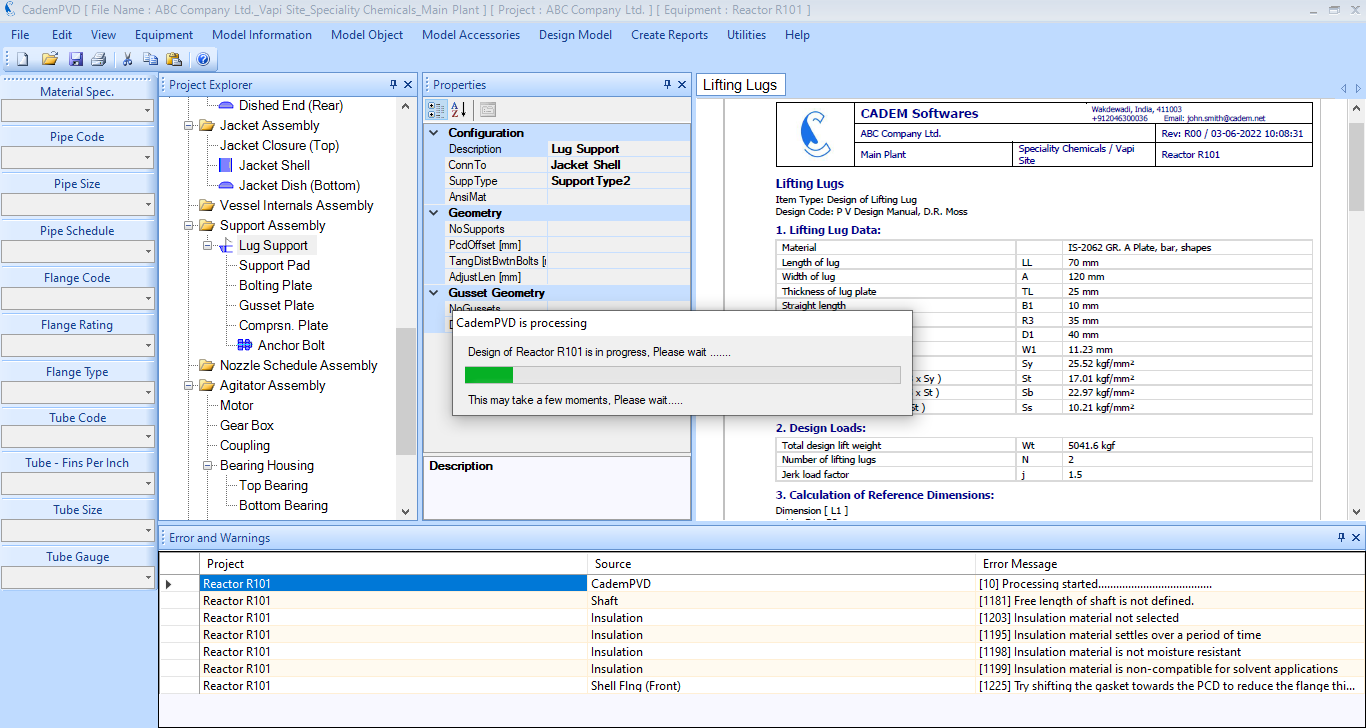
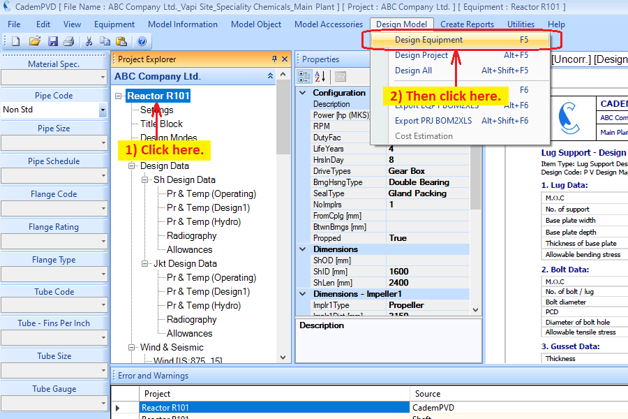
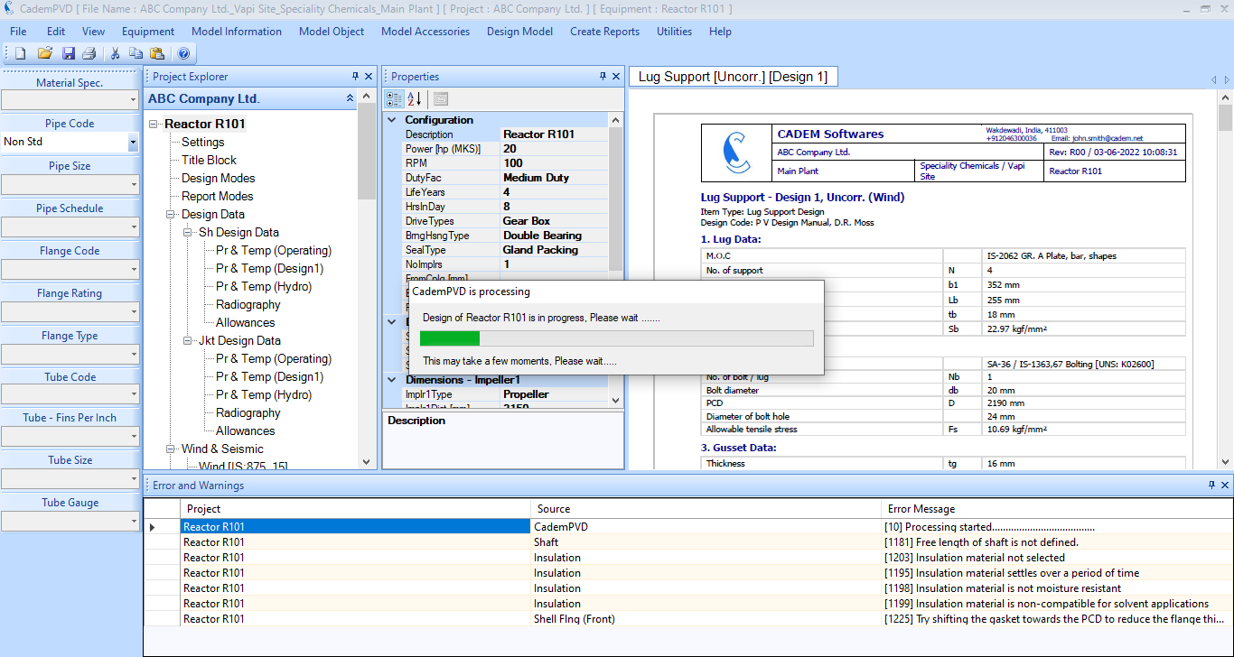
22. At this stage, let us proceed to the design of the equipment. Select the submenu 'Design Equipment', in the top menu 'Design Model', to begin the design of the equipment.
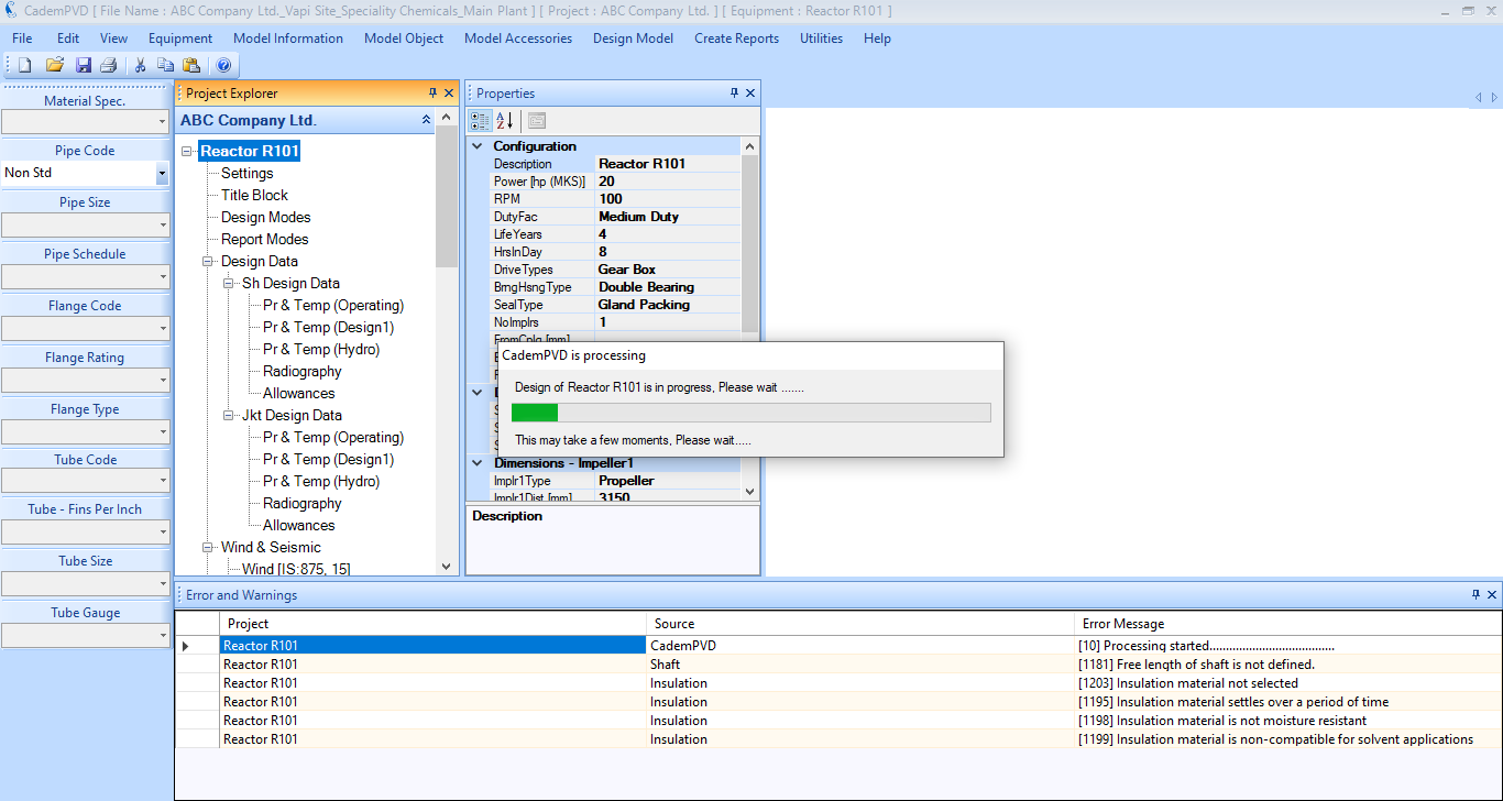
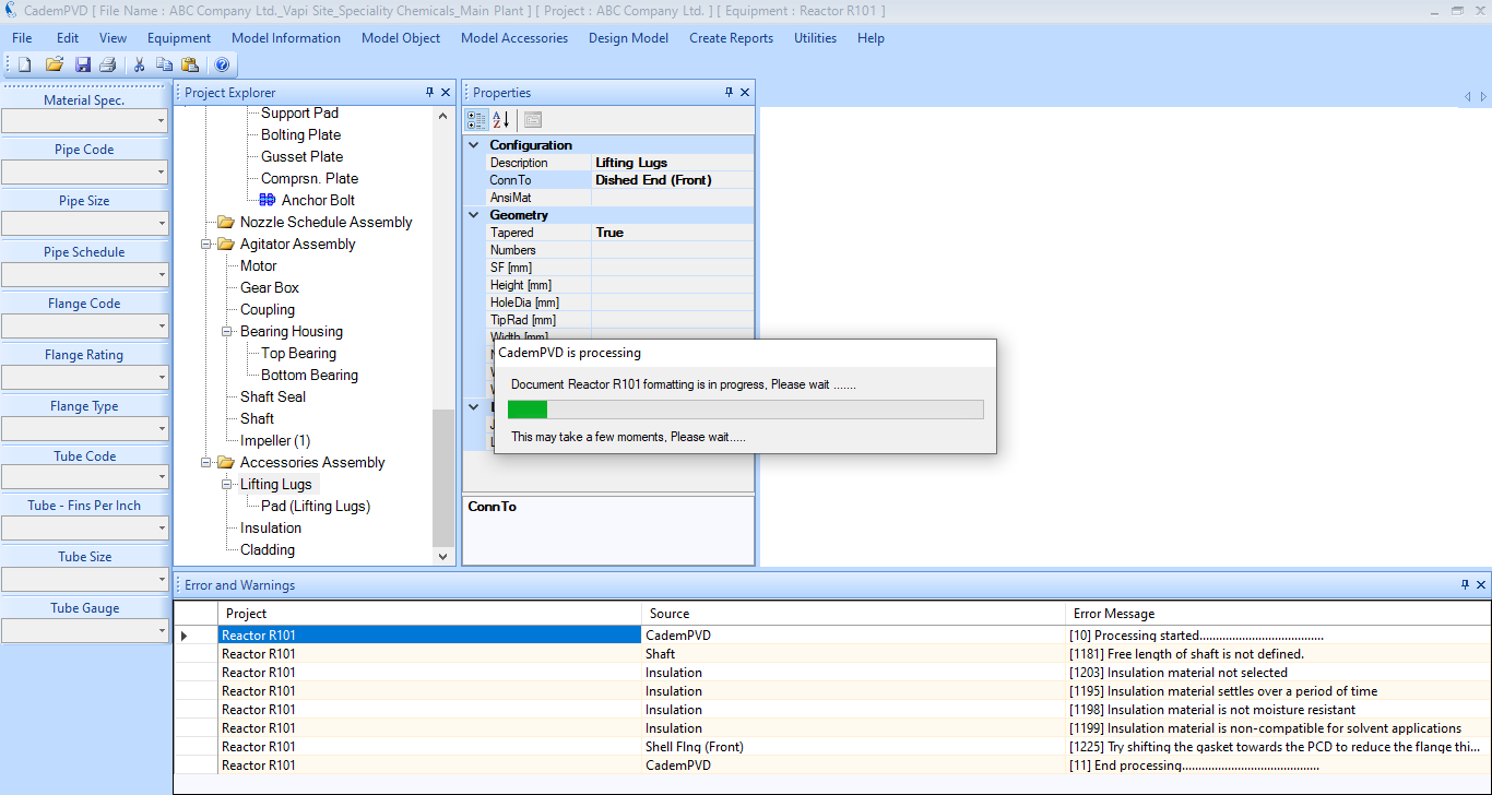
23. While the equipment is designed, any design warning or errors that occur are displayed in the “Errors & Warnings” window. The warnings are displayed in black colour and any severe errors present are displayed in red colour. In the case of Warnings, the user can review them and take necessary corrective action, if required. While in case of Errors, the user has to take necessary corrective action for equipment design to proceed further.
You can notice that there are certain warnings only and there are no errors displayed in the “Errors & Warnings” window.
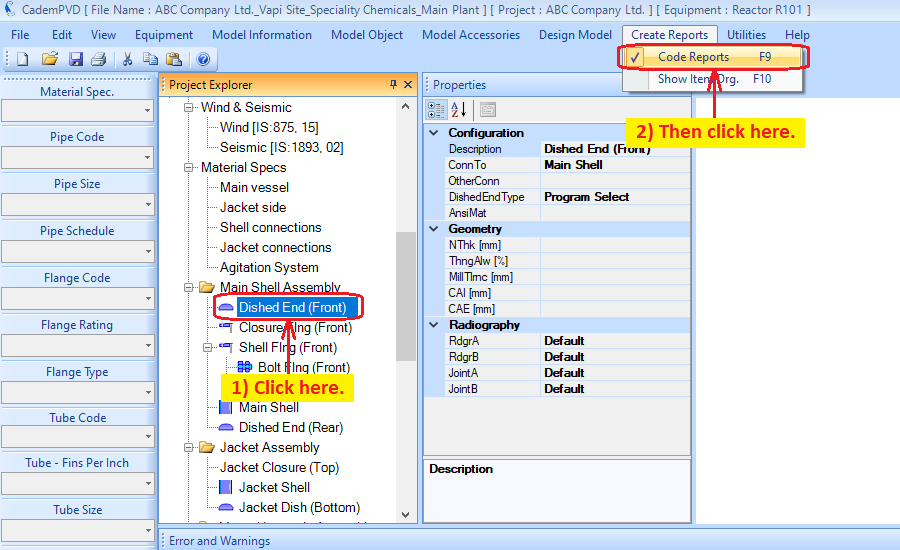
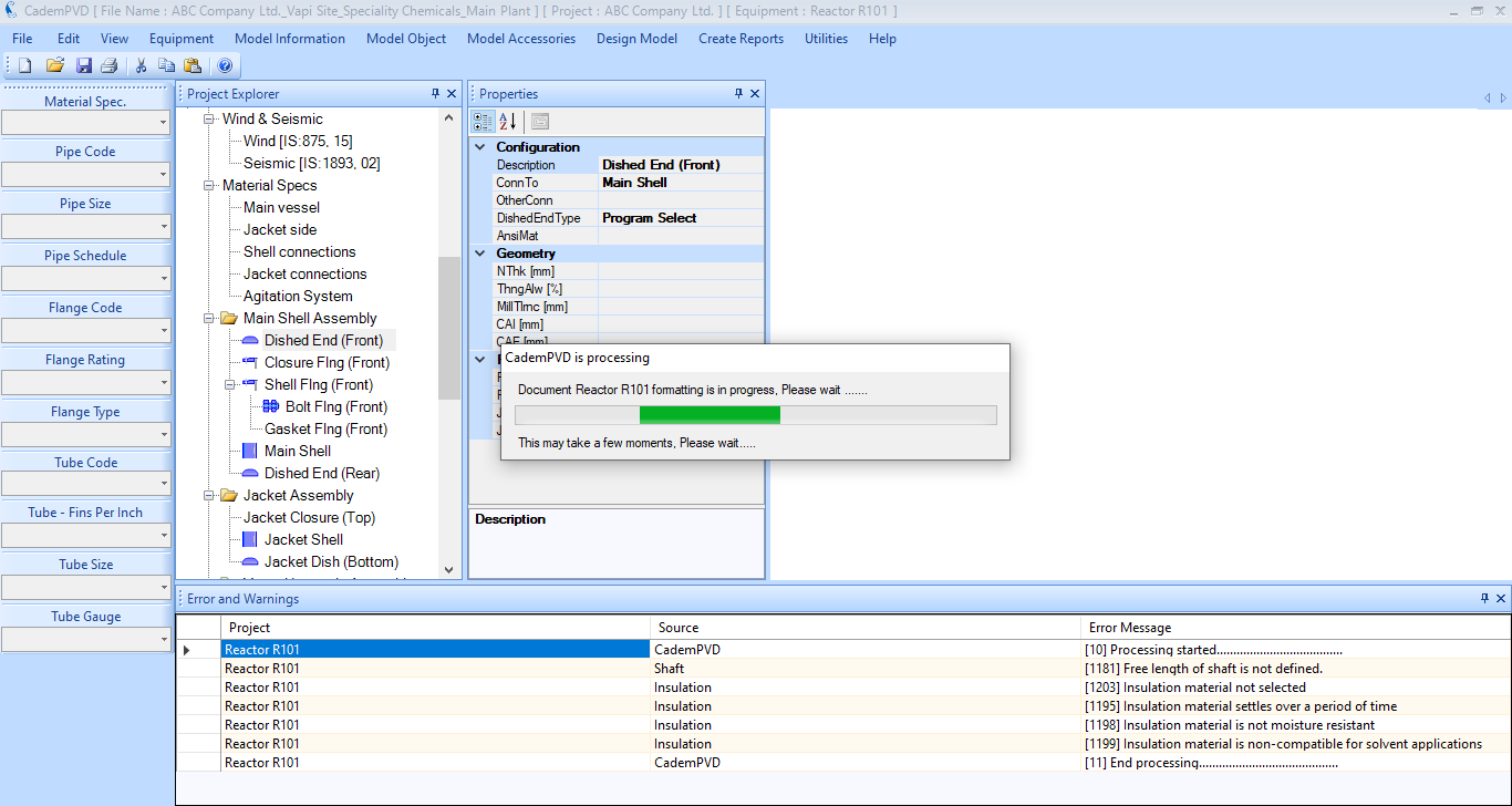
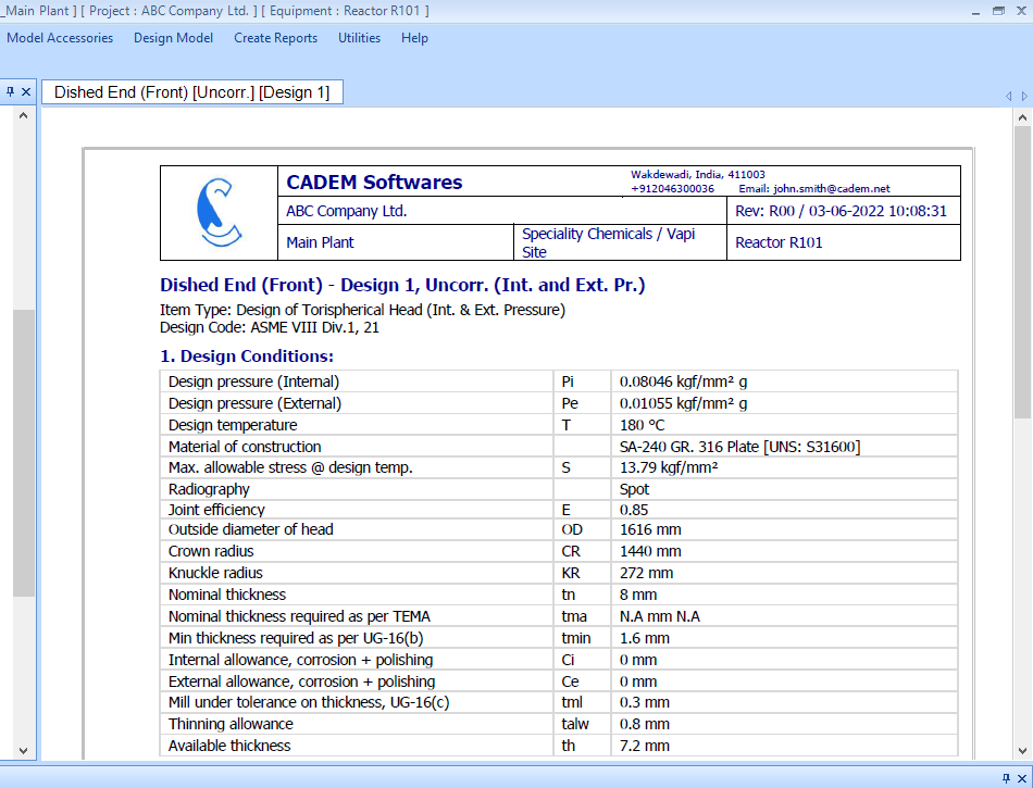
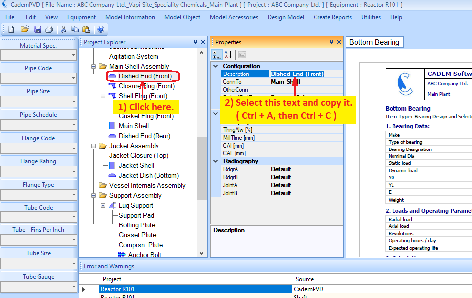
24. Having designed the equipment, proceed to see the design output for the top dish end, 'Dished End (Front)'.
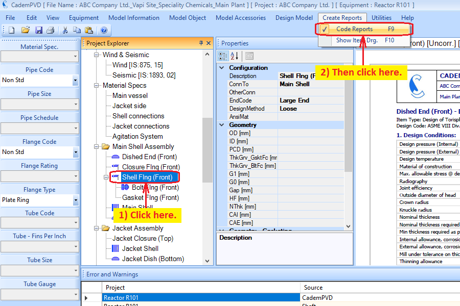
25. Similarly, generate the report for the 'Shell Flange (Front)'.
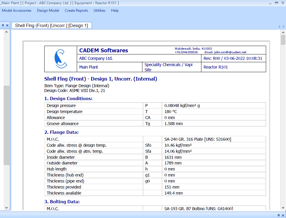
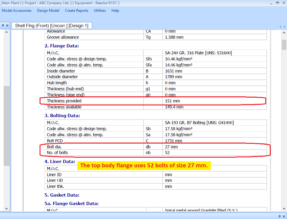
26. Change the flange material and configuration to forged 'SA 182 F316' of type - Fabricated WN.
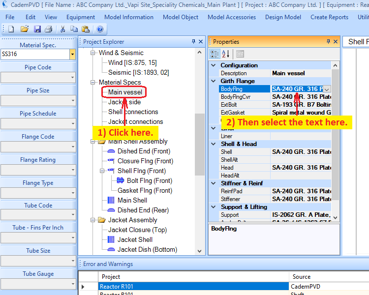
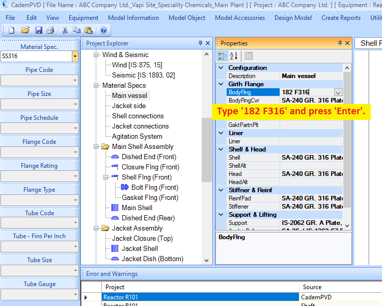
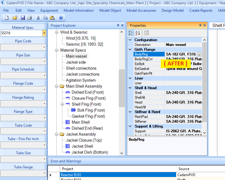
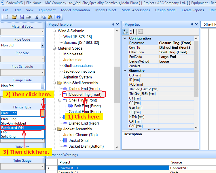
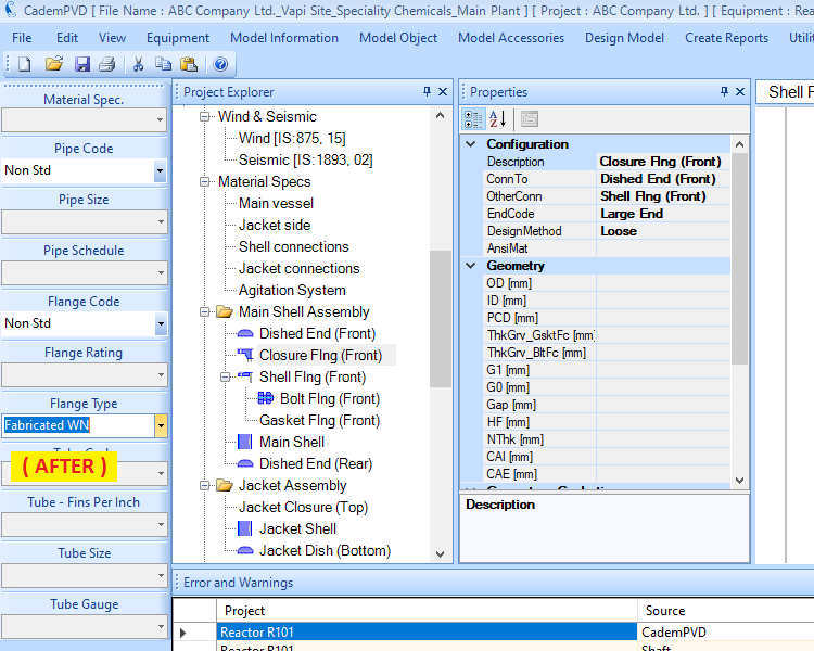
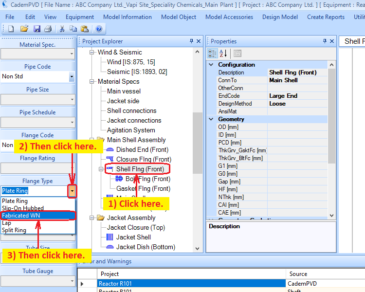
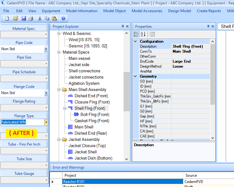
27. Proceed to redesign the equipment and generate the report, and the changes will be reflected in the same.
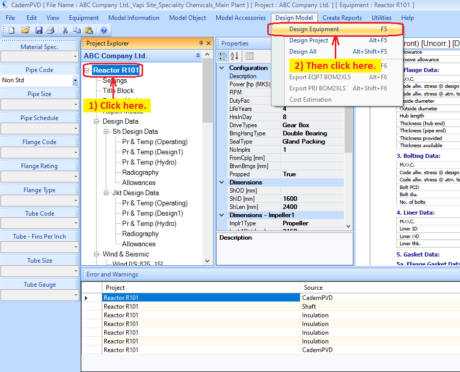
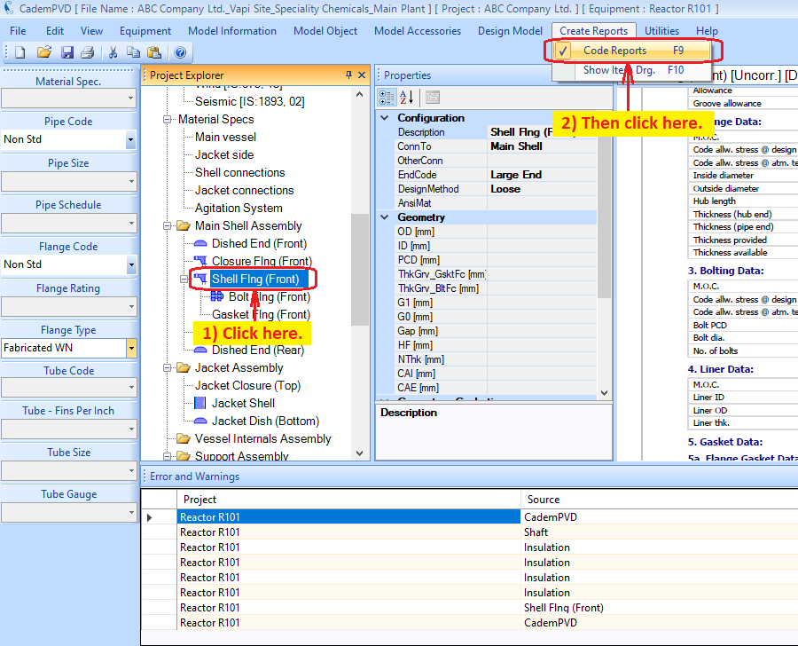
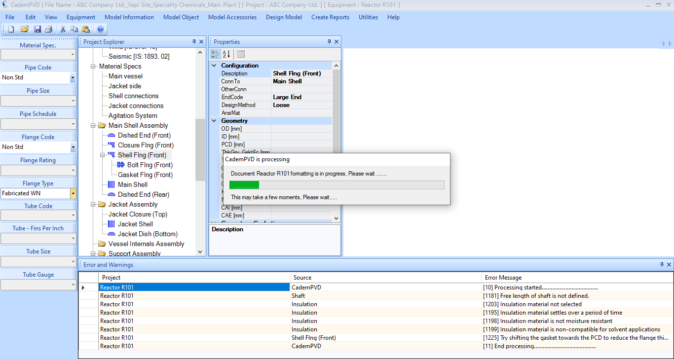
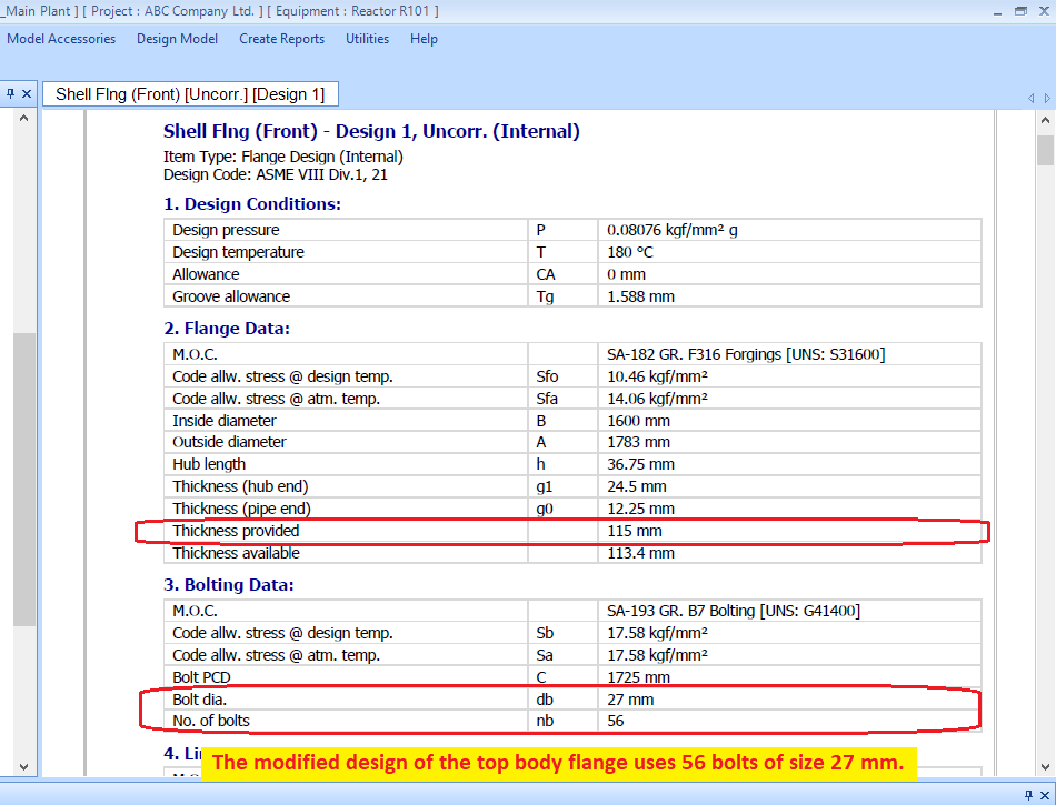
28. Click on the subentry, 'Shaft' and generate the report for it.
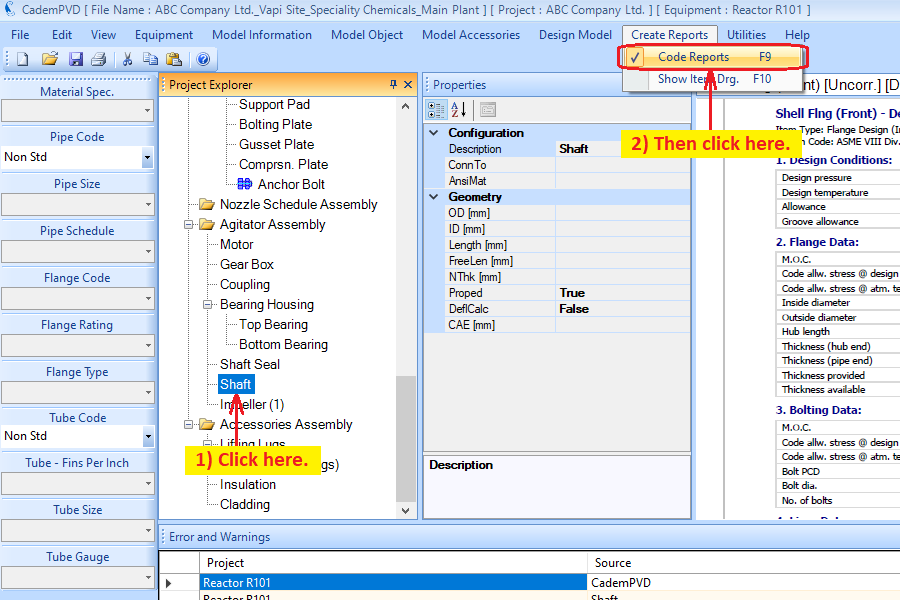
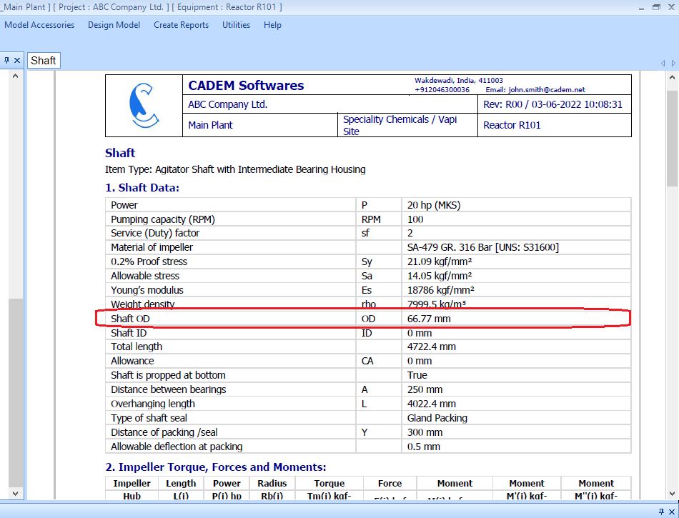
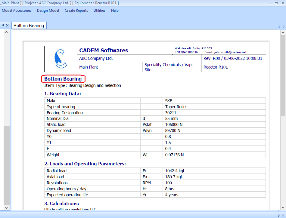
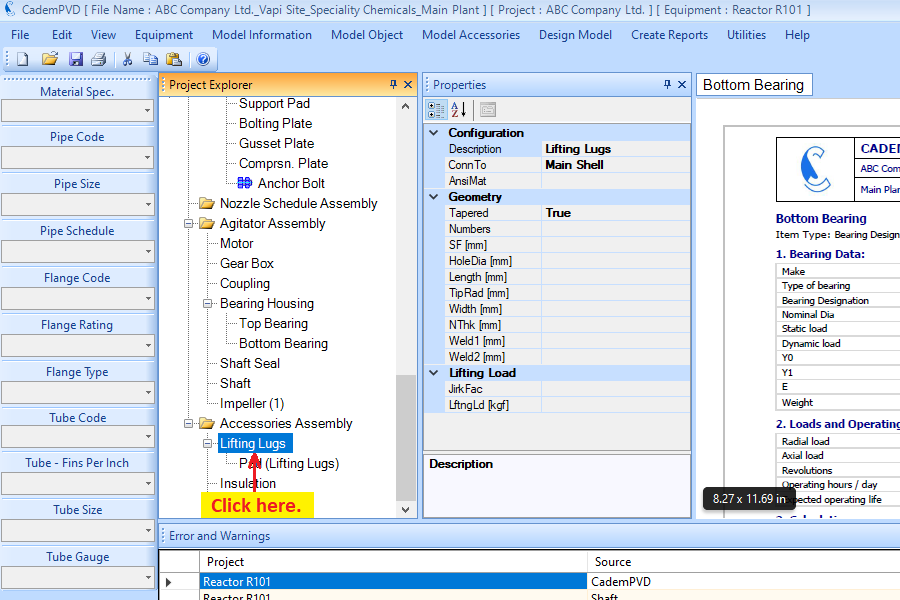
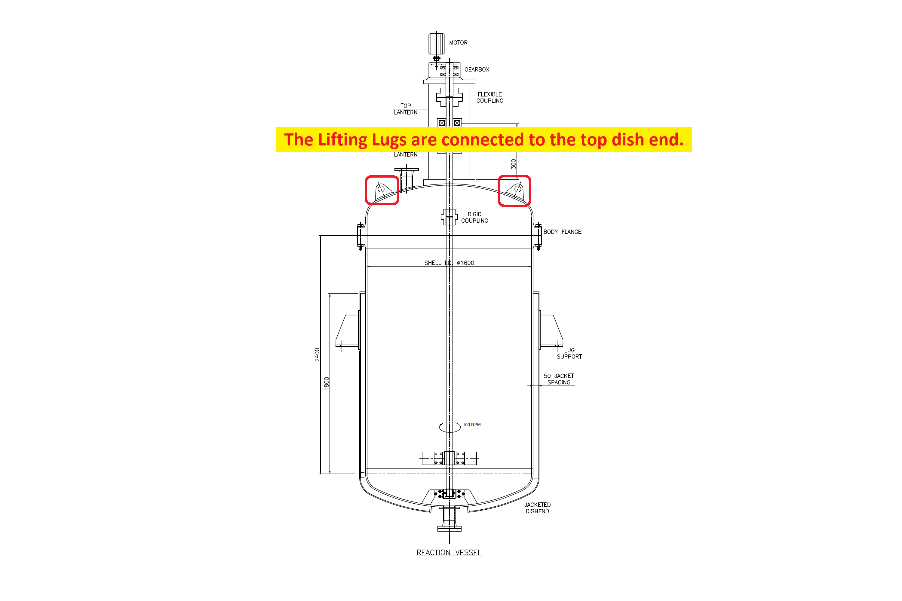
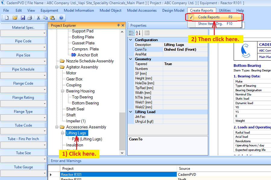
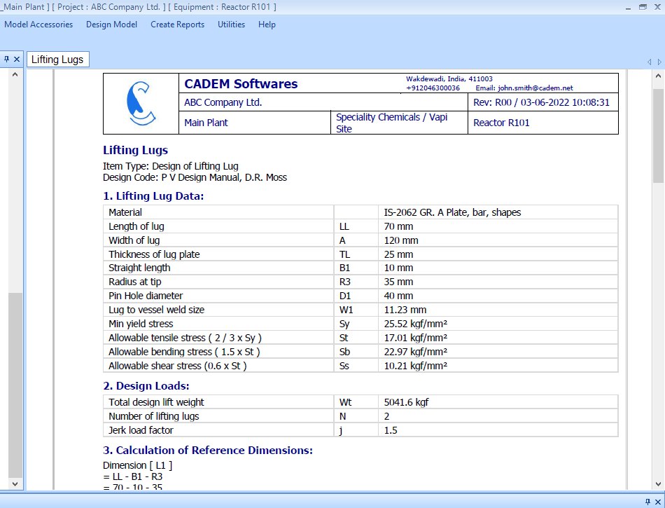
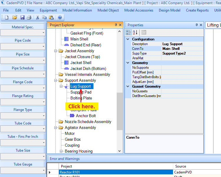
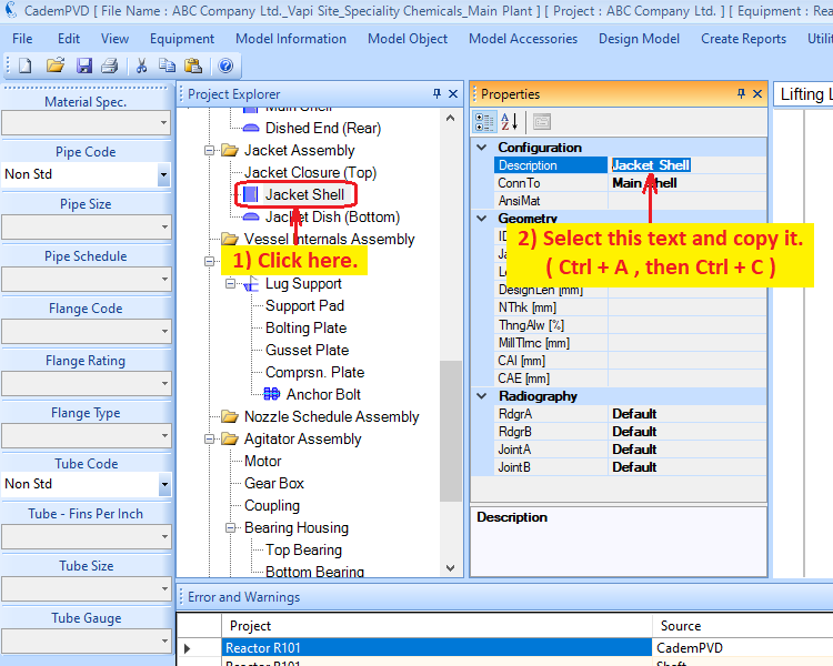
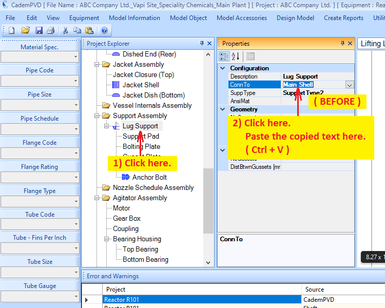
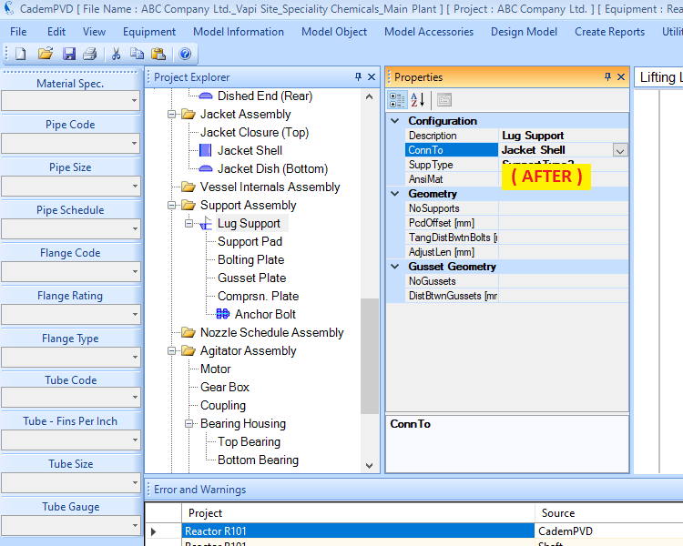
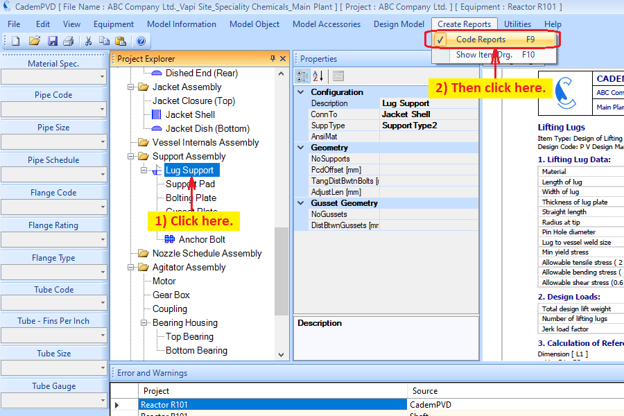
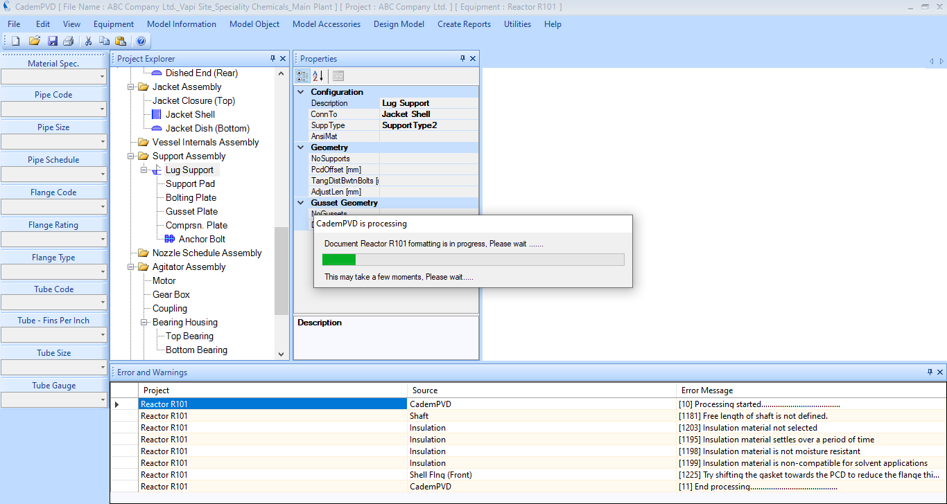
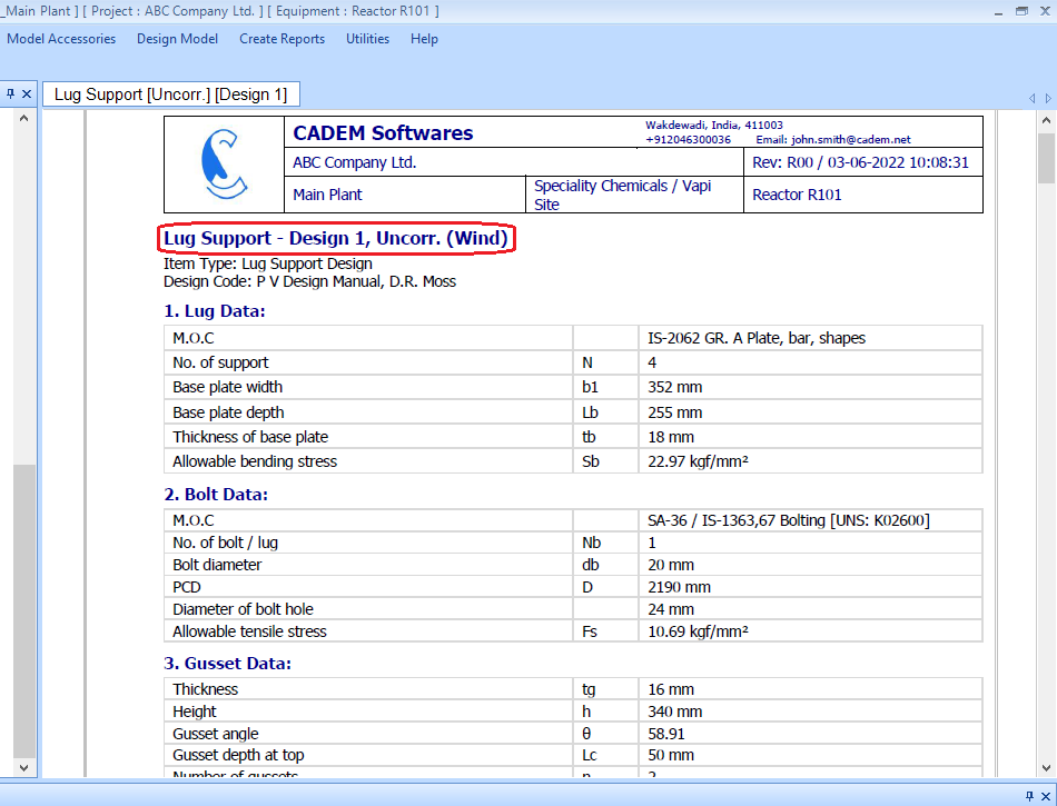
29. Similarly, you can generate the report for the other items, like the top and bottom bearings, lifting lugs and lug supports.
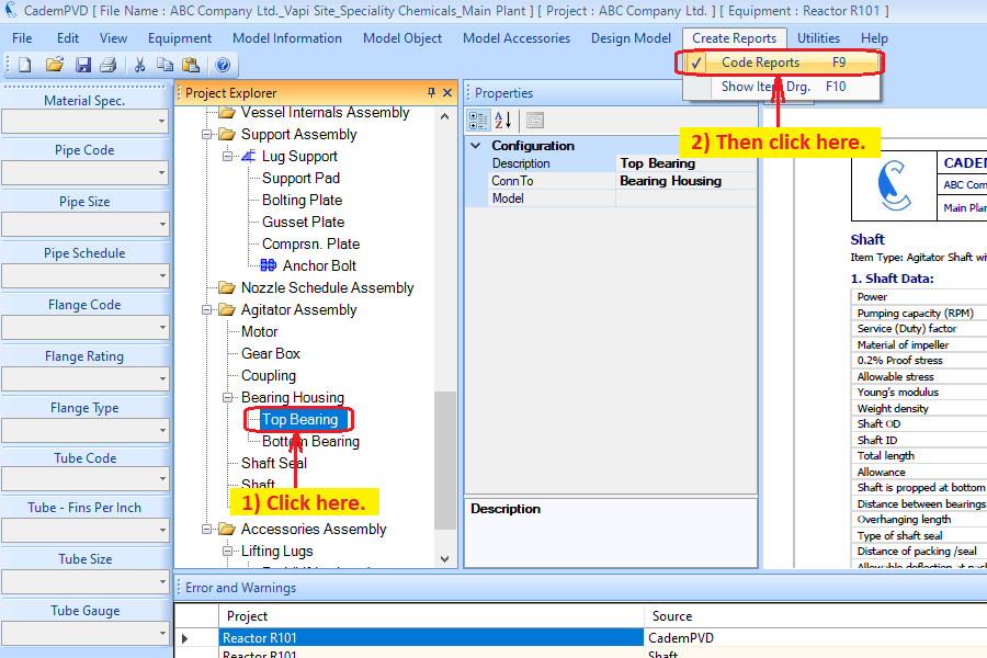
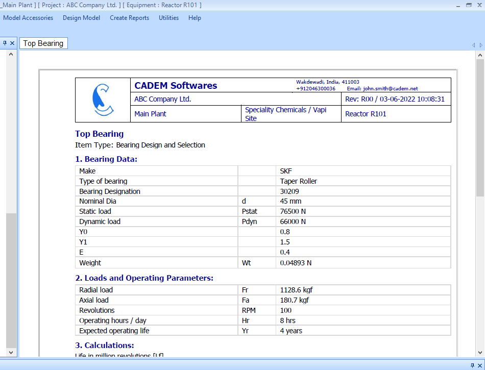
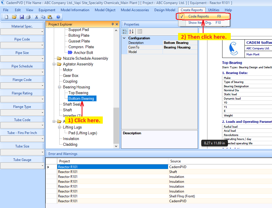
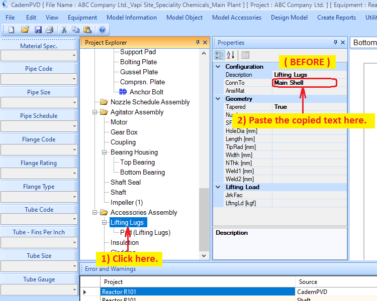
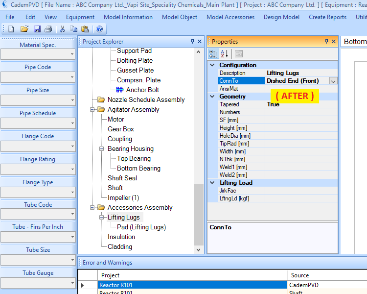
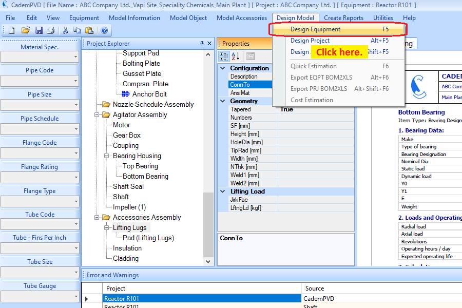
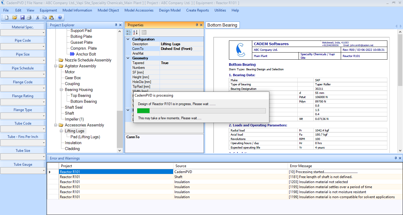
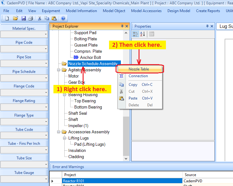
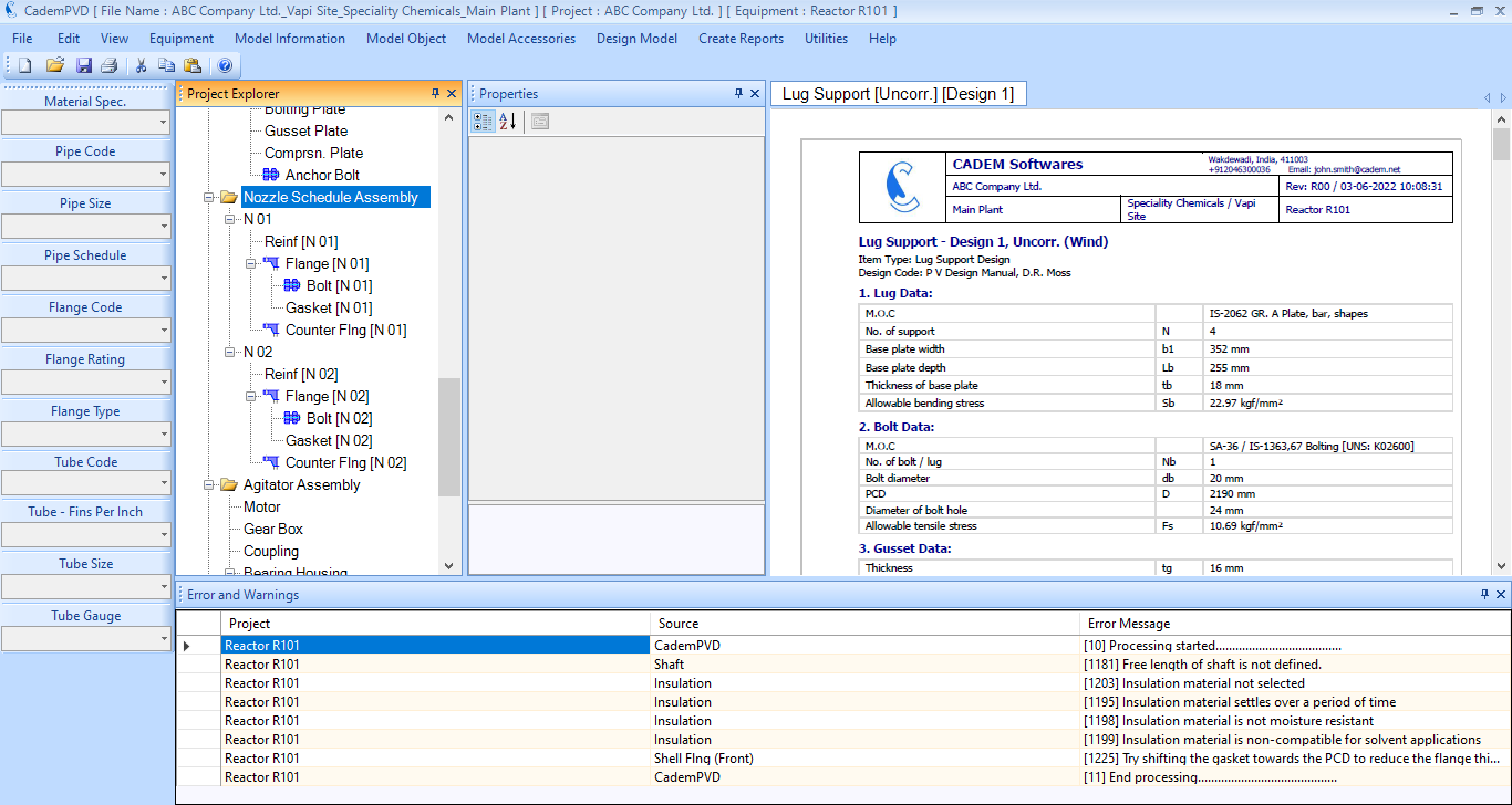
30. Proceed to add nozzles for the equipment as depicted in the images below.


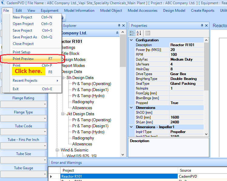
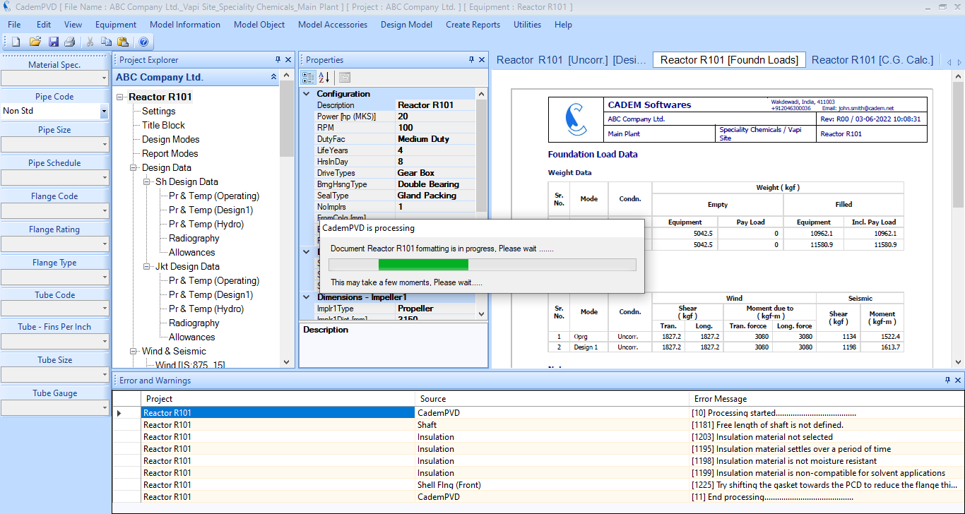
31. After designing the equipment, you can view its report. You can view the foundation load data in the generated tabbed report. To view a consolidated report of the designed reactor, click on the submenu, 'Print Preview', under the 'File' menu.
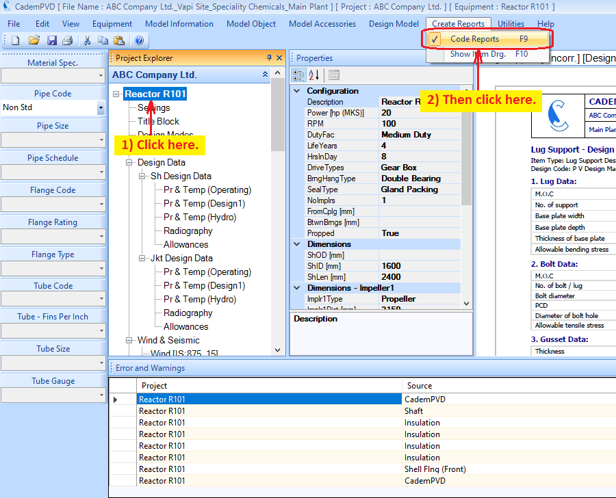
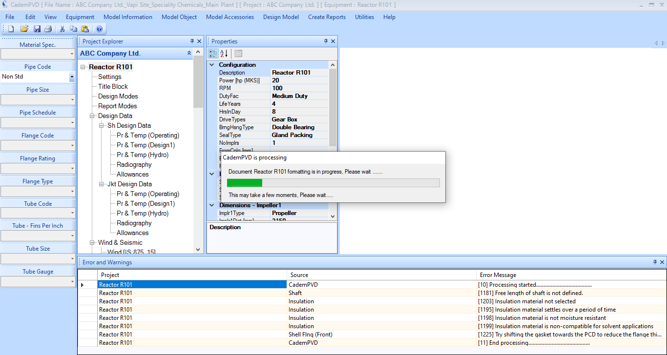
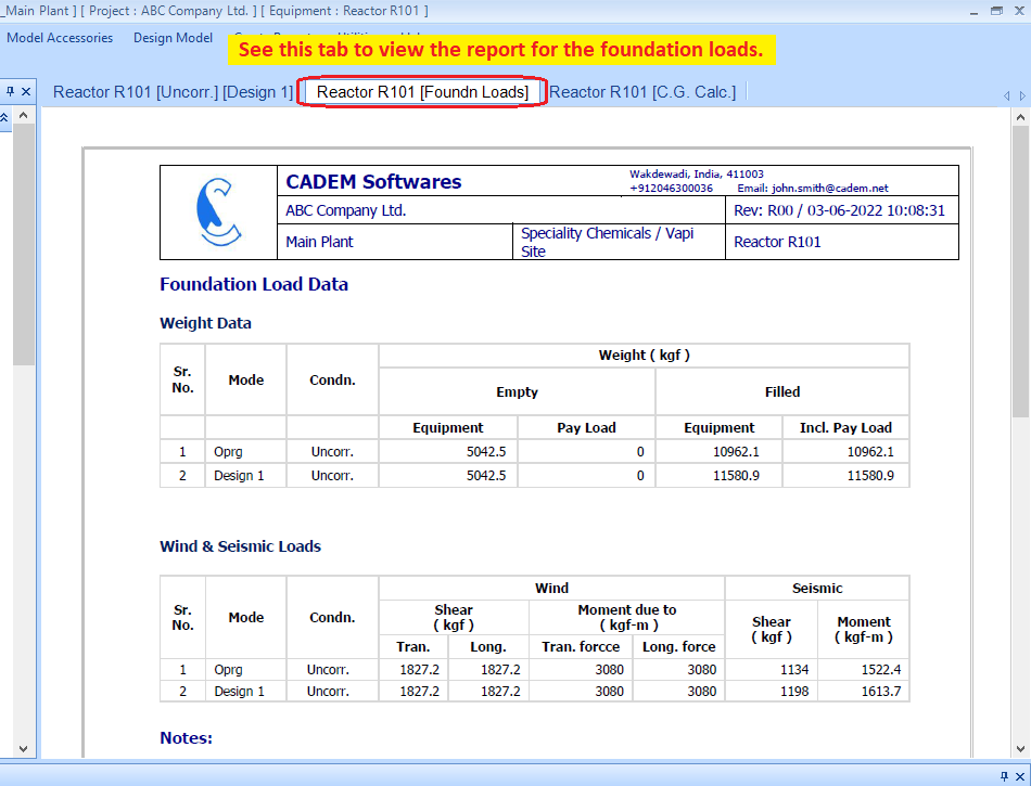
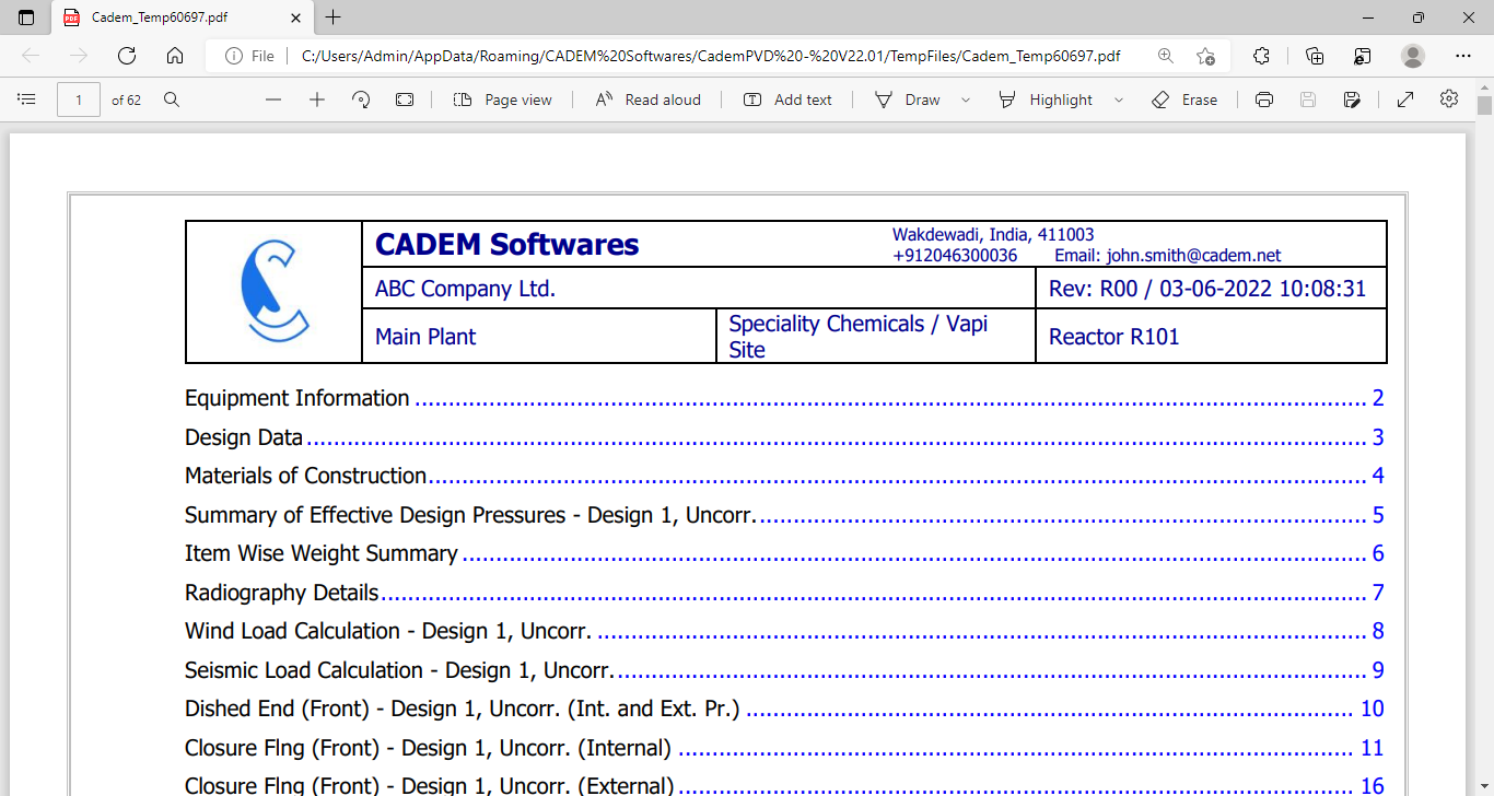
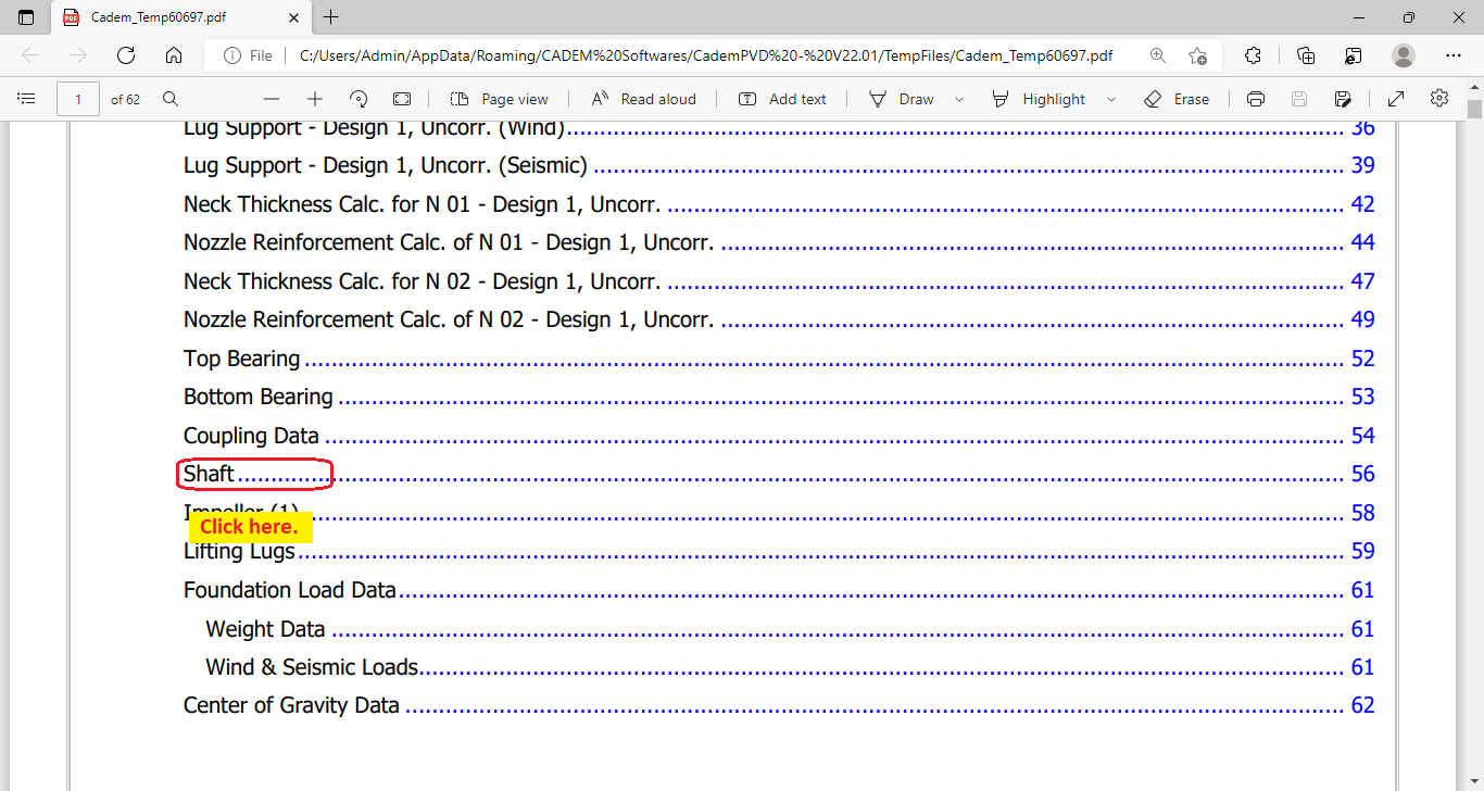
32. You can view the design calculations of any item in the above generated reaction vessel design report.
1A7D8RE9
This completes the tutorial on the design of a reaction vessel with an agitator shaft using CademPVD software.
